


Updated 23/05/07RAOM0507 Apollo Bicycle Company Pty. Ltd. ABN: 60 001 914 469
40
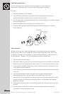
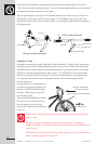
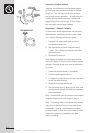
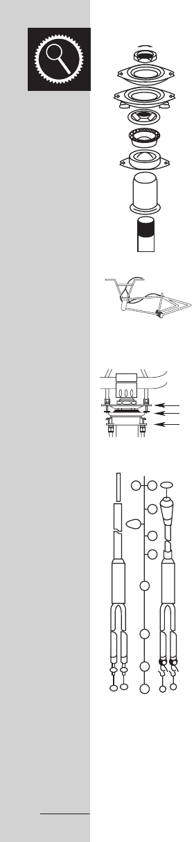
Rotor Headset
A rotor is a special headset mechanism used on some BMX Freestyle
bikes. It enables the handlebars to be turned 360 degrees without
tangling the brake cables. In this system the front brake cable is
connected to the right control lever via the hollow headstem and the
fork. The rear brake cable is split at the rotor bearing mechanism,
activating the rear brake by transferring the left control lever pressure.
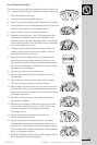
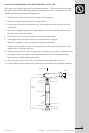
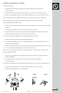
Rotor Installation and Adjustment
Installing and adjusting a rotor headset can be quite a complex
task and one you may refer to your professional bicycle mechanic.
However, if you feel capable the process for rotor installation and
adjustment is listed below.
- Remove fork (H) and upper headset cup (F) from your bicycle.
- Place lower cable stop (C) on the top of the head tube (G).
Replace and fasten the upper headset cup to the head tube via
the lower cable stop.
- Install headset unit onto the fork neck, except the lock washer
and lock nut.
- Place rotor bearing unit (B) over the head set ensuring the larger
side is facing up.
- Install upper cable lock (A) onto the fork neck. (The original lock
washer is now redundant.)
- Place lock nut (D) onto fork neck and alter the head set as usual.
- Connect the upper cable to the left brake lever. (Discard cable
ferrule provided on the upper cable if your lever is already
equipped with a cable adjuster.) Hook the two cable ends (1) to
the top hooks (B1) of the rotor bearing unit. Screw the adjusting
barrels into the upper cable stop.
- Pull rotor bearing unit downward to pick up the slack of cables.
Adjust the height of bearing unit though the cable adjuster on the
brake lever or cable splitter until the bottom hooks (B2) of the rotor
bearing unit are approximately 1/8” – 1/4” away from the lower
cable stop.
- Run the lower cable under the frame tube with the split cables on
each side of the frame. Hook the two cable ends (1) to the bottom
hooks (B2) of the bearing unit. Screw the adjusting barrels into the
lower cable stop.
- Measure and cut the single measure housing (3A) to the correct
length (Caution: This is the only cable that can be cut to adjust
for different frame lengths.) Connect the cable to the rear brake
calliper in the usual manner.
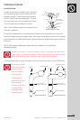
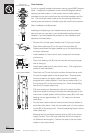
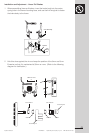
HEAD SET AND
ROTOR ASSEMBLY DIAGRAM
D
A
B1
B
B2
E
F
C
G
H
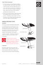
BRAKE
LEVER
UPPER CABLE
ROTOR
LOWER
CABLE
BRAKE
CALIPER
PARALLEL
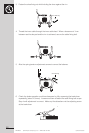
COMPLETE ASSEMBLY
6
7
5
3
3
A
2
4
3
2
1
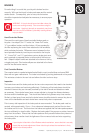
ROTOR CABLE ASSEMBLY
HEAD SET AND
ROTOR ASSEMBLY DIAGRAM
D
A
B1
B
B2
E
F
C
G
H