


13
23
86
20
84
73
Bracket
24
4
114
90
73
37
34
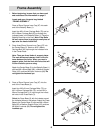
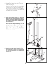
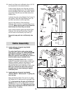
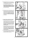
22. Identify the Right and Left Butterfly Arms (19, 20)
by the positions of the welded brackets.
Press a 45mm Square Inner Cap (68) into each
end of the Right Butterfly Arm (19). Wet the lower
end of the Butterfly Arm with soapy water. Slide a
Large Foam Pad (53) onto the lower end of the
Butterfly Arm.
Lubricate the axles on the Butterfly Top Frame (7)
with grease. Orient the Right Butterfly Arm (19)
as shown and slide it onto the right axle.
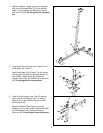
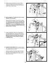
See the inset drawing. Place two 25mm
Retainers (54) on top of an inverted 25mm Cover
Cap (55). Make sure the teeth on the Retainers
bend toward the Cover Cap, as shown.
Have a second person gently tap the two 25mm
Retainers (54) and the 25mm Cover Cap (55)
onto the axle on the Butterfly Top Frame (7).
Repeat this step with the Left Butterfly Arm
(20).
22
7
Lubricate
Axles
Bracket
Welded
Brackets
55
54
68
53
19
68
20
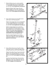
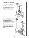
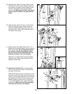
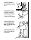
23. Locate and open the parts bag labeled
“CABLE ASSEMBLY.”
For cable identification and routing during
steps 23 to 61, refer to the CABLE DIAGRAMS
and CABLE ID CHART on pages 30 and 31.
Make sure that the cable traps do not touch or
bind the cables as you assemble them.
Identify the Butterfly Cable (73). It is approxi-
mately 52” long and it has an eyelet on each end.
Attach the Butterfly Cable to the bracket on the
Left Butterfly Arm (20) with an M8 x 20mm
Shoulder Bolt (84) and an M8 Nylon Locknut (86).
Make sure that the flat side of the eyelet on
the cable (see the inset drawing) is against
theButterfly Arm.
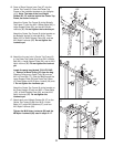
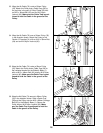
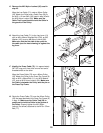
24. Locate and open the parts bag labeled
“PULLEY BAG 2.” Remove one “V”-pulley (34)
from the bag.
Wrap the Butterfly Cable (73) over the “V”-pulley
(34). Attach the “V”-pulley and a Long Cable Trap
(37) to the bracket on the back of the Butterfly
Upright (4) with an M10 x 58mm Bolt (114) and
an M10 Nylon Locknut (90). Make sure the Long
Cable Trap is oriented to hold the Cable in the
groove of the “V”-pulley.
Cable Assembly
Teeth
Axle
54
55
Flat
Side