


17
9
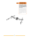
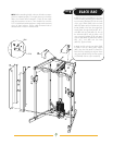
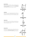
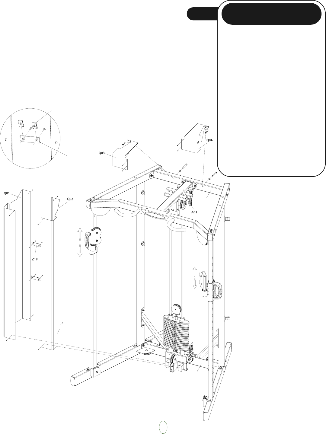
STEP
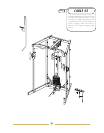
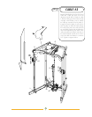
• Slide the slip-on nuts (B26) over the holes
of the connecting brackets (Z19). Attach the
two connecting brackets (Z19) to the inside
of the right shield (Q02) with two bolts
(M5x10). Make sure the brackets are posi-
tioned parallel to the floor when tightened.
Loosely fasten the right shield to AB1, AC1,
and AB2 with four bolts (M5x15). Line up
the left shield (Q01) with the holes in the
rear connecting brackets (Z19) and attach
with two bolts (M5x10). Attach the shield to
AB1, AC1, and AB2 with four bolts
(M5x15). Tighten all bolts.
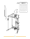
• Attach the left and right top shields (Q03
& Q04) to the top center pulley support
(AB1) using four bolts (M5x15). Attach the
back of the top shields to the top rear frame
using two bolts (M10x70), four flat washers
(10.2x22x2) and two nylon nuts (M10).
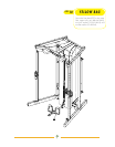
BLACK BAG
AB2
AB2
AC1
AC1
Z19
B26
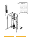
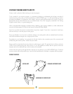
NOTE:
Before assembling shields, make sure all cable connection
points are adjusted properly. The weight selector pin should be
able to be inserted without obstruction. Check all three cable
ends that accessories connect to. There shouldn’t be more than
0.75” of cable slack (cable travel prior to weight stack movement)
at any of these locations. Tighten cable termination bolts to
decrease slack or loosen to increase slack.