6300/6310 Treadmill Electronics Repair Manual – Incline
6300/6310 Incline System Operation
Display Board
Drive Board
Incline Motor
2 pin
Motor
Voltage
Incline
Command
Transformer
Output
16 PIN
Incline VR
Signal
LED3 - Incline Down
LED4 - Incline Up
Incline VR
3 pin
VR
Output
INCLINE.01
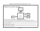
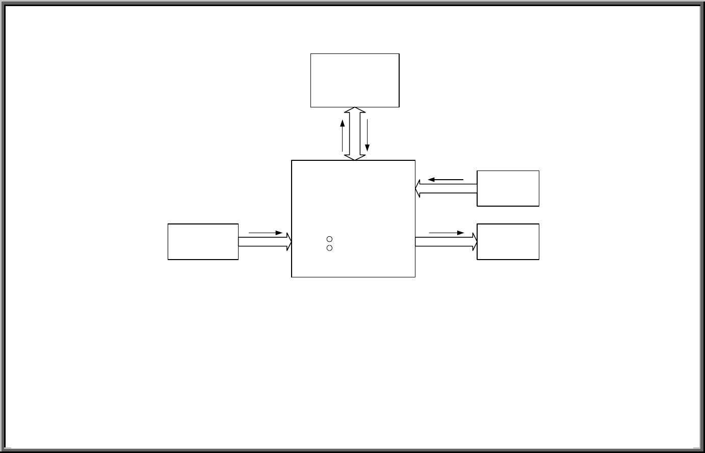
1. Display emits the incline signal, which travels from the ribbon cable to the drive board.
2. The transformer breaks wall power down into smaller voltages for various circuit operation, including the incline motor.
3. The drive board puts out power for the motor. Up operation: K4 relay clicks, LED 4 lights. Down operation: K2 relay clicks, LED 3 lights.
4. The incline motor operates according to power from the drive board. UP operation: K4 relay clicks, LED 4 lights. Down operation:
K2 relay clicks, LED 3 lights.
5. As the incline motor moves, the variable resistor (VR) moves, changing VR output voltage. The VR voltage travels to the drive
board, up the ribbon cable, to the display.
6. The display program IC uses the VR signal to determine the position of the incline. This is used to determine whether to supply or
cut off power for incline motor operation.


