


TROUBLESHOOTING
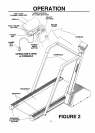
Console and Motor System
Four components make up the console and motor system; FAST TRAC FITNESS COMPUTER, mounted on the
console, INTERFACE BOARD, mounted on the bottom motor cover, MOTOR CONTROLLER and MOTOR mounted
to the front right rail.
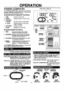
Console
The CONSOLE contains the FAST TRAC FITNESS COMPUTER which controls the speed and elevation of the
treadmill. It also displays time, speed, distance (miles and laps), calories, and pulse.
The time will display from 0:00 to 99:00 inone minute increments. The speed will read between .5 and 10.0 at .1 MPH.
The distance is indicated in miles (0 to 49 3/4) and laps (0 to 199). The calories will be displayed from 0 to 990 in 10
calorie increments.The pulse displays your heart rate from 90 to 180 in 1 beat per minute increments. The time,
distance, calories, and pulse desired can be programmed into the fitness computer.
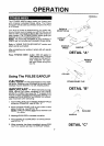
Interface Board
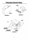
The interface board is an electronic circuitboard mounted tothe bottom motor cover- see FIGURE 3. With the treadmill
plugged in and the power key inserted the DC voltage from PI to N on the interface board should be 13.6 VDC. The
voltage from P2 to N will vary with the speed;
0 MPH - 0 VDC
.5 MPH - .68 VDC
10.0 MPH - 12.3 VDC
The voltage across the capacitor, Cl, should be 9.56 VDC. When the treadmill is runningat .5 MPH the motor should
maintain 250 RPM, at 10.0 MPH the motor should maintain 5200 RPM.
Motor Controller
The motor controller is an electronic circuitboard mounted to the right rail infront of the motor - see FIGURE 4. From
a grounded wall outlet the motor controller receives 120 VAC and converts it to variable DC 0 to 90 V. The monitor
and interface board adjust the output of the motor controllerfrom 0 to 90 volts.The motor controller senses the motor
speed by the tachometer. The tachometer on the motor tells the motor controller itsspeed. If a load is placed on the
treadbelt the motor controller compares the set point of the speed control to the tachometer and makes adjustments
to the DC output voltage to the motor keeping the treadbelt runningat a fixed speed. For example, the output voltage
will be 9.5 volts at .5 MPH, as a person steps on the treadbelt the output voltage increases to compensate for the
extra motor loading, keeping the treadbelt runningat .5 MPH.
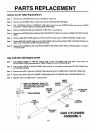
Motor
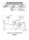
This treadmill uses a 2 HP DC motor - see FIGURE 5. When the voltage to a DC motor is changed the speed will
vary accordingly. The motor receives 0-90 VDC from the motor controller. The voltagefrom M1to M2 while the treadmill
is running at 10.0 MPH should not exceed 90 VDC and the shouldbe turningat 5200 RPM. The motor has an integral
tachometer which tells the motor controllerthe motor's speed. The tachometer consistsof a coil of wire inside a plastic
housing. A permanent magnet mounted to the motor, behind the fan, rotates inside the tachometer coil generating a
low voltage, proportional to the motor speed.
.66 VAC - 250 RPM
9.40 VAC - 5200 RPM
The tachometer coil should be 300 ohms 25 ohms.
Note: The tachometer can be measured with an ohmmeter only when disconnected from the motor controller.
The winding resistance should be very low, approximately 1 ohm. Test each winding in the armature (the rotating part
inside the motor) by slowly rotatingthe motor shaft 1 complete revolution. All windings should be less than 2 ohms.
Note: The windings of the motor can be measured with an ohmmeter only when disconnected from the motor
controller.
9