


PARTS REPLACEMENT
Reset Switch (33) Replacement
Step 1. Remove MOTOR COVER (43).
Step 2. Remove wires from RESET SWITCH (33), one at a time to ensure proper attachment and install on new
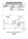
RESET SWITCH. Refer to SPEED CONTROL SYSTEM WIRING DIAGRAM on page 12 if necessary.
Step 3. Remove RESET SWITCH (33) from POWER CORD BRACKET (31).
Step 4. Reinsert RESET SWITCH (33) into POWER CORD BRACKET (31) and attach MOTOR COVER (43).
Console (46), Fitness Computer (46a), And/Or Power Switch Replacement
Step 1.
Step 2.
Step 3.
Step 4.
Step 5.
Step 6.
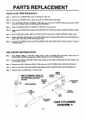
Remove CONSOLE attaching SCREWS (63).
Slip CONSOLE (46) out of CONSOLE TUBE (40).
Remove four SCREWS(46o) and one SCREW (46m) attaching FITNESS COMPUTER (46a) to CONSOLE
BOTTOM (46b).
To replace FITNESS COMPUTER (46a), unplug FITNESS COMPUTER (46a) from WIRING HARNESS
(46g) and plug in new FITNESS COMPUTER.
NOTE: Rep/ace any monitor casing needed.
To replace POWER SWITCH (46k), remove wires from POWER SWITCH and attaching SCREW (461),
snap POWER SWITCH out of the CONSOLE BOI-rOM (46b) and replace with new POWER SWITCH.
Reassembly in reverse order - see SPEED CONTROL SYSTEM WIRING DIAGRAM if necessary.
Wiring Harness (46g) Replacement
Step 1.
Step 2.
Step 3.
Step 4.
Step 5.
Step 6.
Step 7.
Step 8.
Step 9.
Step 10.
Step 11.
Step 12.
Step 13.
Remove MOTOR COVER (43).
Remove CONSOLE (46) - see CONSOLEAND/OR POWER SWITCH REPLACEMENT.
NOTE: Steps 2 through 6 required for UPPER WIRING HARNESS replacement.
Remove BLACK wires from INTERFACE BOARD (73).
Remove BROWN wire from RESET SWITCH (31).
Remove LARGE CONNECTOR from INTERFACE BOARD(73),
Pull UPPER WIRING HARNESS (64g) from CONSOLE TUBE (40).
Remove SMALL CONNECTOR from INTERFACE BOARD (73).
Steps 7 through 12 required for LOWER WIRING HARNESS replacement.
Remove GRAY and BLUE wire from MOTOR CONTROLLER (42).
Remove REED SWITCH (23) - see REED SWITCH REPLACEMENT.
Remove WHITE wires from INTERFACE BOARD (73).
Remove WHITE wire from MOTOR CONTROLLER (42).
Remove LOWER WIRING HARNESS.
Replace WIRING HARNESSES and reinstall in reverse order. Refer to SPEED CONTROL SYSTEM
WIRING DIAGRAM to assure proper wiring.
15