


ADJUSTMENTS
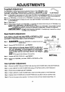
Treadbelt Adjustment
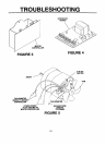
The TREADBELT (12) has been factory pre-adjusted. However, ifthe TREADBELT shifts
to one side or the other, follow these steps to readjust it - see FIGURE 2. Adjust
TREADBELT ADJUSTMENT SCREW (56) by usingthe ALLEN WRENCH (70) provided. ALLEN WRENCH
Step 1. If TREADBELT has moved to right,tighten rightTREADBELT ADJUSTMENT SCREW 1/2 turn usingALLEN
WRENCH, while TREADMILL is running and no one is on it. The TREADBELT should move towards left.
Step 2. Let TREADMILL run several turns of TREADBELT and note any sideways movement.
Step 3. If only a small amount of change occurred, loosen left TREADBELT ADJUSTMENT SCREW 1/2 turn using
ALLEN WRENCH.
Step 4. Repeat step 2.
Step 5. Repeat steps 1 through 4 until TREADBELT iscentered and remains there during use. If TREADBELT has
moved to LEFT, follow steps 1-4 but start with LEFT side.
NOTE: ff TREADBEL T is slipping it will be necessary to tighten both TREADBEL T ADJUSTMENT SCREW
until slipping has stopped. It may then be necessary torepeat steps 1 through 4 for alignment.
_D_L_L_'. DO NOT OVERTIGHTEN TREADBEL 7".Overtightening is denoted by curling of
the edges of the TREADBEL T.
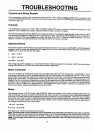
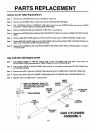
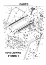
Reed Switch Adjustment
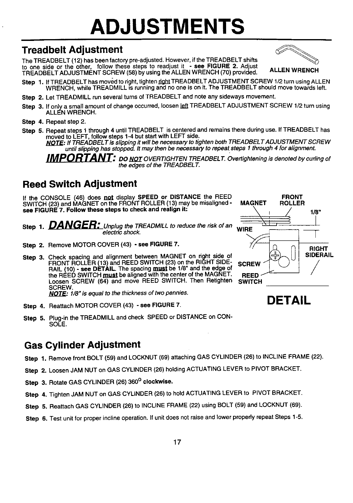
If the CONSOLE (46) does not display SPEED or DISTANCE the REED
SWITCH (23) and MAGNET on the FRONT ROLLER (13) may be misaligned -
see FIGURE 7. Follow these steps to check and realign it:
Step 1. _L__Unplug the TREADMILL to reduce the risk of an
electric shock.
Step 2,
Step 3.
Step 4.
Step 5.
Remove MOTOR COVER (43) - see FIGURE 7.
Check spacing and alignment between MAGNET on right side of
FRONT ROLLER (13) and REED SWITCH (23) on the RIGHT SIDE-
RAIL (10) - see DETAIL. The spacing must be 1/8" and the edge of
the REED SWITCH must be aligned with the center of the MAGNET.
Loosen SCREW (64) and move REED SWITCH. Then Retighten
SCREW.
NOTE: 1/8" is equal to the thicknessof two pennies.
Reattach MOTOR COVER (43) - see FIGURE 7.
Plug-in the TREADMILL and check SPEED or DISTANCE on CON-
SOLE.
FRONT
MAGNET ROLLER
/
WIRE
0
REED/J _----
SWITCH
DETAIL
118"
I
F
RIGHT
SlDERAIL
/
Gas Cylinder Adjustment
Step 1. Remove front BOLT (59) and LOCKNUT (69) attaching GAS CYLINDER (26) to INCLINE FRAME (22).
Step 2. Loosen JAM NUT on GAS CYLINDER (26) holding ACTUATING LEVER to PIVOT BRACKET.
Step 3. Rotate GAS CYLINDER (26) 360 ° clockwise.
Step 4. Tighten JAM NUT on GAS CYLINDER (26) to hold ACTUATING LEVER to PIVOT BRACKET.
Step 5. Reattach GAS CYLINDER (26) to INCLINE FRAME (22) using BOLT (59) and LOCKNUT (69).
Step 6. Test unit for proper incline operation. If unit does not raise and lower properly repeat Steps 1-5.
17