


PARTS REPLACEMENT
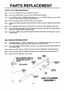
Motor (35b) And Or Flywheel Pulley (35c) Replacement
Step 1. Remove MOTOR COVER (43).
Step 2. Loosen LOCKNUT(69) on J-BOLT (53) to remove DRIVE BELT (36) from FLYWHEEL PULLEY (35c).
Step 3. To replace the FLYWHEEL PULLEY (35c), remove FLYWHEEL PULLEY from MOTOR (35c) by holding
the motor shaft with a STANDARD screw driver and turning the flywheel clockwise. Install new Flywheel
Pulley On Motor
Step 4. Remove Motor wires from MOTOR CONTROLLER (42) and GREEN wire on RIGHT SIDERAIL (10).
Step 5. Remove two MOUNTING STRAPS (35d) attaching MOTOR (35b) to MOTOR MOUNT (35a).
Step 6. Remove MOTOR (35b) with FLYWHEEL PULLEY (35c).
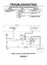
Step 7. Reattach MOTOR (35b) and FLYWHEEL PULLEY (35c) in reverse order usingSPEED CONTROL SYSTEM
WIRING DIAGRAM - see page 12 to assure proper wiring. Make sure the GROUND WIRES (GREEN) are
attached to the RIGHT SIDERAIL (10) and LOCKWASHER (62) is against the SIDERAIL.
Motor Controller (42) Replacement
Step 1. Remove MOTOR COVER (43).
Step 2. Remove wires, one at a time to assure proper attachment, and install onto new MOTOR CONTROLLER
(42). Refer to SPEED CONTROL SYSTEM WIRING DIAGRAM - see page 12 to assure proper wiring.
Step 3. Remove two SCREWS (64) attaching MOTOR CONTROLLER (42) to RIGHT SIDERAIL (10).
Step 4. Reattach MOTOR CONTROLLER (42) to RIGHT SIDERAIL (10) with two SCREWS (64).
Step 5. Reattach MOTOR COVER (43).
Interface Board (73) Replacement
Step 1. Remove MOTOR COVER (43).
Step 2. Remove wires, one at a time to assure proper attachment, and install onto new INTERFACE BOARD (73).
Refer to SPEED CONTROL SYSTEM WIRING DIAGRAM - see page 12 to assure proper wiring.
Step 3. Remove CIRCUIT BOARD SUPPORTS (54) attaching INTERFACE BOARD (73) to BO]-rOM MOTOR
COVER (44).
Step 4. Attach new INTERFACE BOARD (73) to BOTTOM MOTOR COVER (44) using CIRCUIT BOARD SUP-
PORTS (54).
Step 5. Reattach MOTOR COVER (43).
Reed Switch (23) Replacement
Step 1.
Step 2.
Step 3.
Step 4.
Step 5.
Step 6.
Step 7.
Step 8.
Remove MOTOR COVER (43).
Remove SCREW (64) attaching REED SWITCH (23) to RIGHT SIDERAIL (10).
Unplug CONNECTOR END of REED SWITCH (23) from INTERFACE BOARD (73).
Route new REED SWITCH (23) wire in same location as old REED SWITCH wire.
Install REED SWITCH (23) to RIGHT SIDERAIL (10) with SCREW (64) and TOOTH LOCKWASHER (62).
NOTE: Make sure TOOTH LOCKWASHER is on SIDERAIL side.
Plug CONNECTER END of REED SWITCH (23) intoINTERFACE BOARD (73).
Adjust REED SWITCH (23) - see "ADJUSTMENT" sectionfor proper method of adjusting REED SWITCH.
Reattach MOTOR COVER. 14