


9
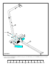
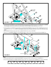
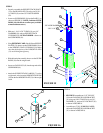
FIGURE 7
STEP 7
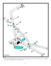
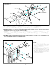
FIGURE 8
STEP 8
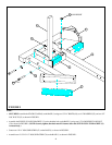
• Attach both 2 X 16-1/2” PLATES (14) to the bushing on the BACK PAD SUPPORT (10) using one 1/2 X 5-1/2” BOLT (69) and one 1/2”
LOW HEIGHT LOCK NUT (54). (NOTE: Securely tighten, then back nut off 1/4 turn to allow the 2 X 16-1/2” PLATES (14) to rotate
freely.)
• Attach BACK PAD SUPPORT (10) to the WOLFF SLEEVE (12) using one 1/2 X 4” BOLT (68) and one 1/2” LOCK NUT (53). (NOTE:
Securely tighten, then back nut off 1/4 turn to allow the BACK PAD SUPPORT (10) to rotate freely.) See FIGURE 7.
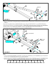
• Slide one HINGE TAB (40) on each side of shaft on WOLFF SLEEVE (10) as shown in FIGURE 7.
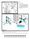
• Stick one 1-1/4” RUBBER BUMPER (70) on the BENCH FRAME (2) where it makes contact with the BACK PAD SUPPORT (10).
• Securely attach BACK PAD (22) to BACK PAD SUPPORT (10) using two 3/8 X 2-3/4” (65) and two 3/8” WASHERS (51).
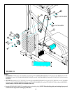
• Securely attach SEAT PAD (23) to HINGE TABS (40) using two 3/8 X 1-1/4” (63) and two 3/8” WASHERS (51) as shown in FIGURE 8.
69 1/2 X 5-1/2”
68 1/2 X 4”
51
51
40
23
22
10
53
10
12
40
54
14
3/8 X 2-3/4” 65
3/8 X 1-1/4” 63
1/2” LOW
HEIGHT
70
2
0
1
2
345
6
1/2 1/2 1/2 1/2 1/2 1/2