


12
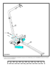
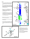
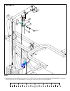
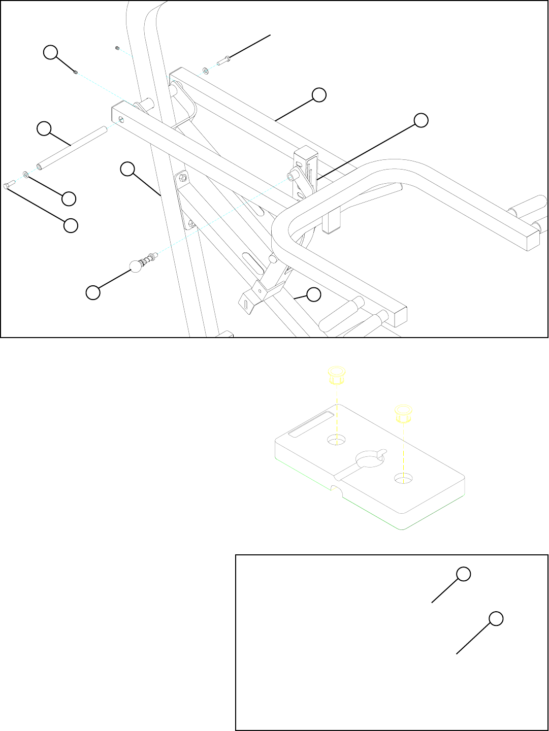
FIGURE 13
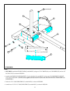
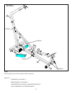
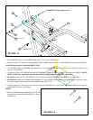
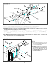
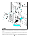
FIGURE 14
STEP 14
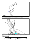
• Snap two WEIGHT PLATE BUSHINGS (28) each, into
the top side of fifteen WEIGHT PLATES (31) as shown
in FIGURE 13.
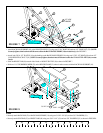
STEP 13
31
28
3. SECURELY tighten two 5/16” SET SCREWS (57) to the collars on the end of the PRESS ARM (3) as shown in FIGURE 13.
• Slide one 3/4 DIA X 11" SHAFT (25) through PRESS ARM (3), PRESS ARM ADJUST (7), and TOP BOOM (5) as shown in FIGURE 13.
4. SECURELY assemble one 1/2” SPRING PIN ASSEMBLY (37) into the SPRING PIN BARREL on the PRESS ARM (3). Pull back on spring
pin until it engages with one of the slots in the PRESS ARM ADJUST (7).
5
37 1/2” SPRING PIN
7
3
25
57
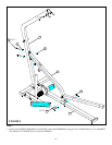
63 3/8 X 1-1/4”
51
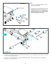
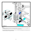
2. Assemble two 3/8 X 1-1/4” BOLTS (63) and two 3/8” WASHERS (51) to the 3/4” DIA X 11” SHAFT (25) as shown in FIGURE 12.(NOTE:
SIMULTANEOUSLY tighten bolts, then back nut off 1/4 turn to allow the PRESS ARM (3) to rotate freely.)
• Slide the PRESS ARM (3) over the PRESS ARM ADJUST (7) as shown in FIGURE 13.
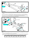
Use the following sequence to tighten the PRESS ARM:
1. Center PRESS ARM (3) and PRESS ARM ADJUST (7) over the BENCH FRAME (2) and have someone firmly hold in place until
sequence 3 is completed..
2
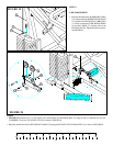
5. If further adjustment is necessary, loosen the bolts securing the TOP BOOM (5) to the BASE (1) and BENCH FRAME (2), reposition
TOP BOOM accordingly and retighten.
IMPORTANT! Follow sequence below.