


14
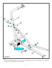
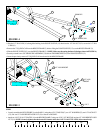
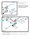
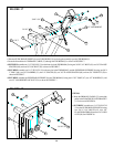
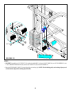
FIGURE 17
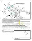
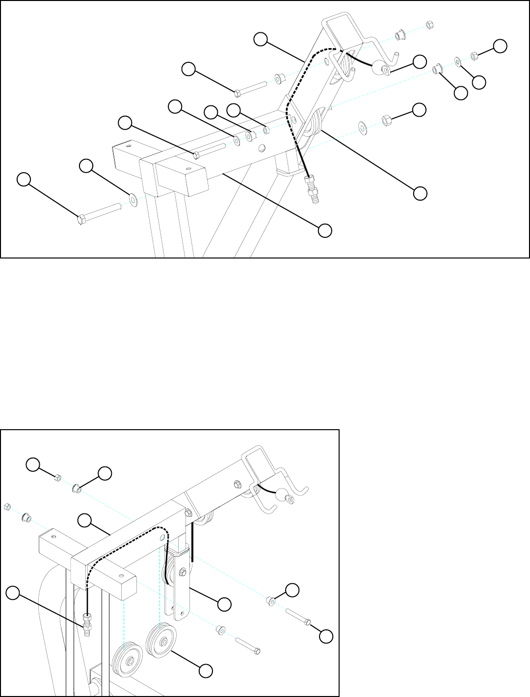
STEP 17
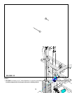
• Slide the GUIDE ROD SUPPORT (6) onto GUIDE RODS (19) and swing the assembly up to the TOP BOOM (5).
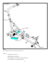
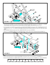
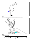
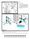
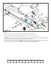
FIGURE 18
STEP 18
3/8 X 3” 66
5
50
60
54 1/2” LOW HEIGHT
55
6
58
60
51
33
67 1/2 X 3”
3/8 X 2-3/4” 65
• SECURELY assemble one 3-1/2” PULLEY (34) to the front slot in the TOP BOOM (5) using one 3/8 X 2-3/4” BOLT (65), two 3/8” FLANGE
SPACERS (60), and one 3/8” LOCKNUT (50) as shown in FIGURE 17.
• Route the threaded end of PRIMARY CABLE (33) through the TOP BOOM (5) as shown in FIGURE 17.
34
• SECURELY assemble one 3-1/2” PULLEY (34) to the rear slot in the TOP BOOM (5) and the GUIDE ROD SUPPORT (6) using one 3/8 X
3” BOLT (66), two 3/8” WASHERS (51), one 1/4” SPACER (58), two 3/8” FLANGE SPACERS (60), and one 3/8” LOCKNUT (50) as
shown in FIGURE 17.
• SECURELY assemble the GUIDE ROD SUPPORT (6) to the TOP BOOM (5) using one 1/2 X 3” BOLT (67), two 1/2” WASHER (55), and
one 1/2” LOW HEIGHT LOCK NUT (54) as shown in FIGURE 17.
• Route the PRIMARY CABLE (33) around the
pulley in the FLOATING PULLEY BRACKET
(11) as shown in FIGURE 18.
• SECURELY assemble two 3-1/2” PULLEYS
(34) to the GUIDE ROD SUPPORT (6) using
two 3/8 X 2-3/4” BOLTS (65), four 3/8”
FLANGE SPACERS (60) and two 3/8” LOCK
NUTS (50). See FIGURE 18.
34
11
60
50
60
6
33
3/8 X 2-3/4” 65
51