


7
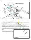
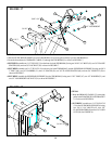
FIGURE 4
0
1
2
345
6
1/2 1/2 1/2 1/2 1/2 1/2
STEP 4
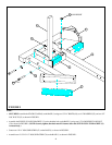
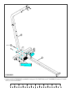
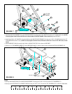
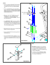
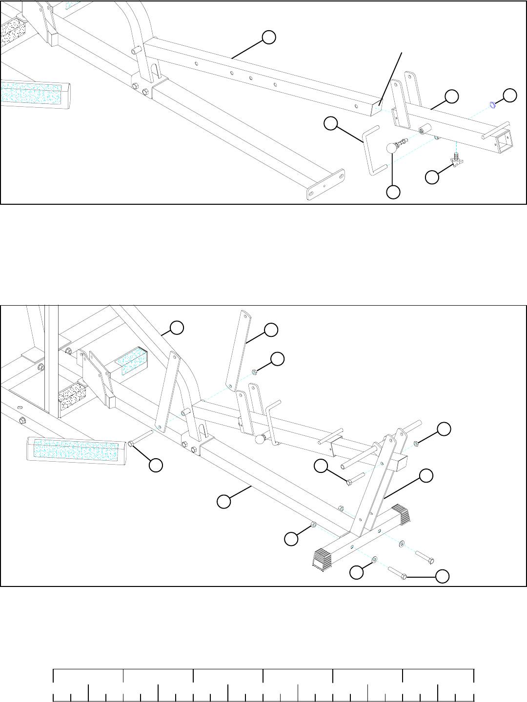
• Slide the WOLFF SLEEVE (12) over the BENCH FRAME (2). (NOTE: Make sure the spring pin barrel is facing as shown in FIGURE 4.)
• Securely assemb1e one 3/8” SPRING PIN ASSEMBLY (36) and one THUMBSCREW (44) to the WOLFF SLEEVE (12).
• Slide the 1/2” DIA U-PIN (41) through the bushing in the WOLFF SLEEVE (12) then force the 1/2” PAL NUT (42) over end of 1/2” DIA
U-PIN (41).
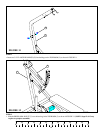
• Attach two 1/4 X 2 X 16-1/2” PLATES (14) to the BENCH FRAME (2) using one 1/2 X 5-1/2” BOLT (69) and one 1/2” LOW HEIGHT LOCK
NUT (54). (NOTE: Securely tighten, then back nut off 1/4 turn to allow the 1/4 X 2 X 16-1/2” PLATES (14) to rotate freely.)
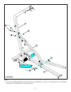
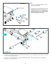
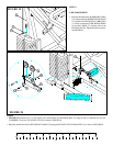
• Loosely assemble the LEG SUPPORT (4) to the BASE (1) using three 1/2 X 3” BOLTS (67), two 1/2” WASHERS (55), one 1/2” LOCK NUT
(53), and one 1/2” LOW HEIGHT LOCK NUT (54) as shown in FIGURE 5.
FIGURE 5
STEP 5
55
53
54 1/2” LOW
HEIGHT
14
54 1/2” LOW HEIGHT
42
36 3/8” SPRING PIN
12
41
44
4
2
2
67 1/2 X 3”
69 1/2 X 5-1/2”
1/2 X 3” 67
1
• Remove the 2” SQ. END CAP from the BENCH FRAME (2) before sliding the WOLFF SLEEVE (12) over the BENCH FRAME (2).
REMOVE!
• Insert the previously removed 2” SQ. END CAP into the end of the BENCH FRAME.