


28
0
1
2
3 4 5
6
1/2 1/2 1/2 1/2 1/2 1/2
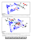
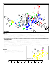
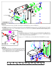
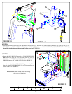
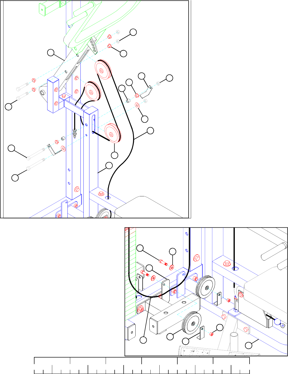
STEP 34:
FIGURE 34
• Route the threaded end of the PRESS
CABLE (44) around one 4-1/2” PULLEY
(48) and SECURELY assemble the pulley
to the front slot of the PRESS ARM AD-
JUST (36) using one 3/8 X 2-3/4” BOLT
(90), two 3/8” FLANGE SPACERS (69),
and one 3/8” LOCK NUT (82) as shown in
FIGURE 34. (NOTE: Loop the cable over
the pulley prior to inserting it into the
slot.)
• Route PRESS CABLE (44) through the slot in
the PRESS BASE (38) then SECURELY as-
semble one 4-1/2” PULLEY (48) to the
PRESS BASE (38) using two 3/8 X 4”
BOLTS (92), two 2-7/8 X 2-1/4” CABLE
CLIPS (116), two 3/8” FLANGE SPACERS
(69), two 3/8 X 1/2” SPACERS (58), two 3/
8” WASHERS (80), and two 3/8” LOCK
NUTS (82) as shown in FIGURE 34.
(NOTE:Make sure the cable is routed be-
tween the pulley and the CABLE RETAIN-
ING BOLT.)
• Route the PRESS CABLE (44) around one
4-1/2” PULLEY (48) and SECURELY as-
semble the pulley to the rear slot of the
PRESS ARM ADJUST (36) using one 3/8
X 2-3/4” BOLT (90), two 3/8” FLANGE
SPACERS (69), and one 3/8” LOCK NUT
(82) as shown in FIGURE 34. (NOTE:
Loop the cable over the pulley prior to
inserting it into the slot.)
82
69
69
58
82
48
38
44
36
90 3/8 X 2-3/4”
92 3/8 X 4”
67
38
48
82
44 PRESS
CABLE
80
89 3/8 X 2”
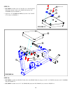
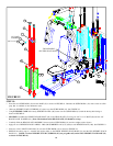
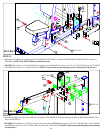
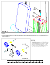
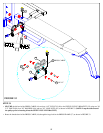
FIGURE 35
24
STEP 35:
• SECURE the PRESS CABLE (44) and two 4-1/2”
PULLEYS (48) to the vertical flats on the PRESS BASE
(38) and on the PRESS WEIGHT STACK BASE (24)
using two 3/8 X 2” BOLTS (89), two 2-7/8” CABLE
CLIPS (67) two 3/8” WASHERS (80), and two 3/8”
LOCK NUTS (82) as shown in FIGURE 35. (NOTE:
The PRESS CABLE (44) should be routed
underneath the short leg of the CABLE CLIP. Also,
the CABLE CLIPS should be positioned straight
down to function properly.)
92 3/8 X 4”
80
116