


41
MEMBRANE PANEL
1. Remove control panel end caps from upright assembly.
2. Remove membrane panel and display board assembly by releasing Velcro.
3. Disconnect upper wire harness from display board.
4. Remove screws securing display to membrane panel.
5. Install new membrane panel.
FACE PLATE (Replaces membrane panel on SPRINT 3 ONLY)
1. Remove control panel end caps from upright assembly.
2. Remove faceplate panel and display board assembly by releasing Velcro.
3. Disconnect upper wire harness from display board.
4. Remove screws securing display to faceplate panel.
5. Install new faceplate panel. NOTE: since the program buttons are located on the display board,
make sure the display board is properly aligned to the new faceplate.
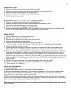
DRIVE MOTOR
1. Elevate treadmill to 15%. Unplug power cord.
2. Remove motor plastic motor cover.
3. Disconnect drive motor wires from motor control board.
4. Remove green ground wire from frame.
5. Remove drive-belt tension adjustment bolt by removing nut.
Nut is located on bottom of motor pan. Note: See section on Tracking and Tensioning
6. Remove drive-belt from drive motor.
7. Locate drive motor hitch pins on bottom of motor pan. Remove hitch pins using needle nose
pliers. Note: When reinstalling hitch pins make sure to crimp ends to insure positive locking.
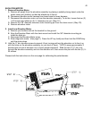
8. Remove motor spacers: The rubber and metal spacers mounted between the motor mount and
motor pan are arranged in a specific manner. The reason for this is to reduce vibration. If your
standing on the treadmill, the following arrangement applies: On the right side you will have (0)
spacers on top of pan and (1) rubber,(1) metal followed by (1) retaining clip on bottom. On the left
side you will have (1) metal spacer on top of the pan and (1) rubber on the bottom followed by (1)
retaining clip.
9. Remove drive motor. Be sure not to lose metal spacer from under right side.
10. When re installing make sure to properly position foam block under motor.
11. Reverse steps for installation.
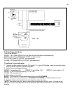
DRIVE MOTOR BRUSHES
1. Unplug treadmill!
2. Remove motor brush caps (2) with large flat head screwdriver.
3. Remove motor brushes and inspect. They should be replaced if 1/4 inch or less. Inspect motor
commutator for wear (black-scoring present on copper segments). Try to dress out (clean up)
commutator with a commutator stone or emery cloth.
4. When you reinstall motor brushes make sure the brush does not bind up in its holder. The motor
brush must move freely the full length with zero resistance. If resistance is present you must carefully
dress out the brush until the correct tolerance is achieved.
Motor brushes should be checked every 6 months on institutional treadmills and after 5 years
on home units.