


39
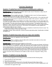
Removal and Replacement of Components
1. Before beginning any removal or replacement of components unplug power cord from wall.
2. Make a note of serial number, model (L7, L8, Home, LTD, or Club) and type (Sport, Pro, Cardio,
CRT, or Executive). Landice tracks all information from this serial number and it must be given
when requesting parts or technical assistance.
3. Always remove one component at a time to test for problems and to simplify replacement.
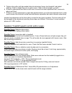
POWER CORD (LINE CORD)
1. Unplug from wall. Remove motor cover screws and motor cover. Follow cord to where it enters
frame. Remove screw holding Green wire to frame and remove Green wire. Remove Blue wire
and Brown wire from motor control board. Remove old cord. Remove strain relief (have a spare in
case it’s damaged in removal). Push new cord through motor pan. Replace Strain Relief. Replace
green ground wire to frame and Blue and Brown wire to motor control board.
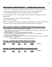
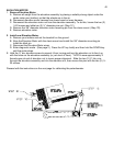
PWM or MOTOR CONTROL BOARD (MCB)– Cut plastic wire ties as needed but remember to
replace them when done! (Use lower wiring schematic for wire colors)
1. Remove wire from L1. This wire connects MCB to Relay Board.
2. Remove wire from L2. This wire connects MCB to Relay Board.
3. Remove wire from A-. This wire connects MCB to Drive Motor.
4. Remove wire from A+. This wire connects MCB to Drive Motor.
5. Remove wire from P1. This wire connects MCB to Relay Board.
6. Remove wire from P2. This wire connects MCB to Relay Board.
7. Remove wire from V+ or P3.This wire connects MCB to Relay Board.
8. Remove four screws attaching board to frame and remove MCB.
9. Reverse to install new MCB.
SCR – LTD and CLUB ONLY (Make sure treadmill is unplugged!)
1. Disconnect elevation motor harness from board.
2. Disconnect speed sensor harness from board.
3. Disconnect upper wire harness from board.
4. Remove Red wire. This connects SCR to Choke.
5. Remove Green wire. This connects SCR to Ground on Frame.
6. Remove Black wire. This connects SCR to Capacitor.
7. Remove White wire. This connects SCR to Capacitor.
8. Remove Black and White wires from connections marked MTR. These connect SCR to Drive
Motor.
9. Reverse to install.
CHOKE- LTD and CLUB ONLY
1. Remove Red wire. This connects Choke to SCR.
2. Remove Purple wire. This connects Choke to SCR.
3. Reverse to install.
CAPACITOR- LTD and CLUB ONLY
1. Remove White wire. This connects Capacitor to SCR.
2. Remove Black wire. This connects Capacitor to SCR.
3. Remove Purple wire. This connects Capacitor to Choke.
4. Remove Resistor. This connects both Poles of the Capacitor.
5. Reverse to install.