


40
12 VDC TRANSFORMER REPLACEMENT (HOME TREADMILLS ONLY)
Observe the proper polarity when installing a new DC power transformer. Catastrophic
damage can occur to the upper display board electronics if the DC polarity is reversed.
1. If your DC transformer has color coded fast-on (push on) connectors:
Blue - negative (-)
Red - positive (+)
2. If your DC transformer has non color coded fast-on (push on) connectors:
Black Wire (smooth) - negative (-)
Black Wire (ribbed) - positive (+)
3. If your DC transformer has pin-type connectors:
Black Wire - negative (-)
Black Wire w/ White strip - positive (+)
4. If you are retrofitting a new style DC transformer (Fast-On) connectors to a treadmill
equipped with (Pin - Type) connectors follow these instructions.
a. Snip the DC output wires six inches from the harness plug with a pair of diagonal
cutters.
b. Snip the FAST-ON connectors from the new DC transformer.
c. Use solderless butt-type connectors to splice the wires together.
d. Use the information listed above to make sure the proper polarity is observed.
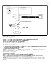
RELAY BOARD (SPRINT 4/PRG/SST CLOSED LOOP ONLY)
1. Remove Orange wire from P1. This wire connects Relay Board to MCB.
2. Remove Brown wire from P2. This wire connects Relay Board to MCB.
3. Remove Purple wire from V+. This wire connects Relay to MCB.
4. Remove two (2) Black wires from DC Transformer. These wires connect Relay Board to DC
Transformer. Note: Wires coming from Transformer are hard wired.
5. Remove Clip for Red, Green, and Black wires. These wires connect Relay Board to Speed Sensor
mounted on Drive Motor.
6. Remove Clip for Blue, Orange, Brown, Red, Black, and White wires. These wires connect to
Elevation Motor.
7. Remove Clip with Red, Brown, Blue, Yellow, White , Black, and Green wires labeled Upper
Harness. This connects the Relay Board to the Upper Display.
8. Remove Four screws and remove board.
9. Reverse to install.
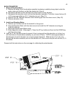
UPPER DISPLAY BOARD
1. Remove control panel end caps from upright assembly.
2. Remove membrane panel and display board assembly by releasing Velcro.
3. Disconnect upper wire harness from display board.
4. Remove screws securing display to membrane panel.
5. Install new display board.