


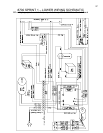
34
terminals with your voltmeter. You should measure 120/220VAC across these terminals. The DC
voltage comes out of the SCR board (going to the drive motor) across two output terminals marked
MTR+ and MTR-. Confirm DC voltage out by measuring across these two terminals with your
voltmeter. You should measure 90/180VDC output. If the SCR board is getting the proper AC voltage
in but does not supply any DC voltage out, it must be replaced.
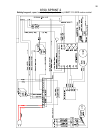
RELAY BOARD
The relay board runs on AC voltage. The AC voltage is delivered to the relay board across two input
terminals marked HOT and NEUT. The AC voltage then passes through one fuse or two (220
models) and lights the AC PWR led light. If this LED light is not on, first check the fuse/s. If the fuse/s
are good measure across the input terminals HOT and NEUT to confirm proper AC voltage in
(110/220VAC). If the relay board is receiving the proper AC voltage in but does not function properly,
it must be replaced.
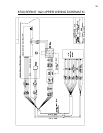
SPEED SENSOR
The speed sensor can be checked for proper operation by entering the Diagnostic Mode.
There is a yellow SPD LED mounted to either the relay board (HOME PWM models) or the SCR
board (LTD and CLUB models). The light will flash ON and OFF when you rotate the drive motor
flywheel slowly by hand. This indicates the proper operation of the speed sensor. If you do not get
this flashing to occur, then check for proper speed sensor alignment. If this does not help, replace the
speed sensor.
UPPER DISPLAY BOARD
The upper display board is powered by DC voltage. On HOME treadmills this DC voltage is supplied
by the DC power supply. On LTD/CLUB treadmills the SCR board supplies this DC voltage. Confirm
the upper display is getting DC voltage delivered to it. If the display board has the proper DC voltage
supplied and does not light, it must be replaced.