


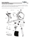
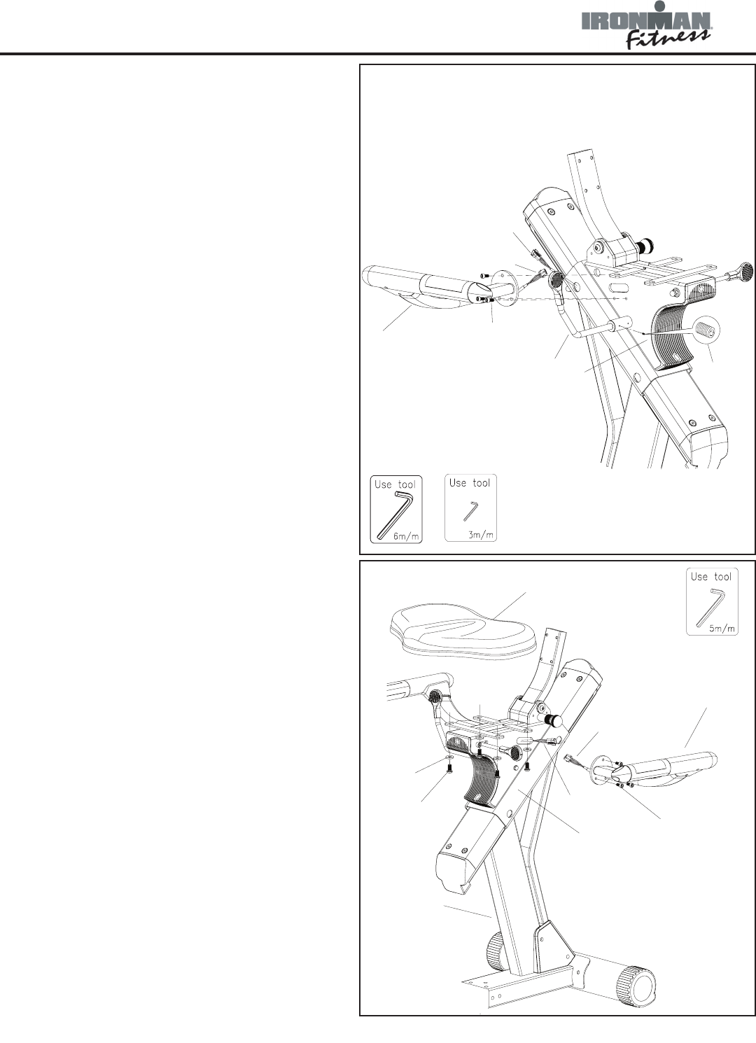
9
Assembly
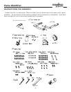
A9
A11
N7
J - (R)
A24
E2 - 1
N10
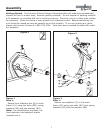
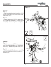
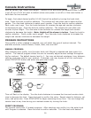
Figure 5
Step 1:
Slide the seat adjustment handlebar (A11)
into the main frame and secure using stop-
ping screw (N10).
Step 2:
Connect sensor wire (A24) to sensor wire
(E2-1) and side handlebar (J-R) onto sliding
track (A9). Secure using three bolts (N7).
Figure 5
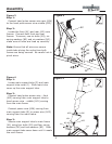
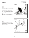
G
N7
J-(L)
E2-2
A9
A24
A2
N1
N3
Figure 6
Step 1:
Connect sensor wire (E2-2) to sensor wire
(A24) and side handlebar (J-L) onto sliding
track (A9). Secure using three bolts (N7).
Step 2:
Locate seat pad (G) and secure onto sliding
track (A9) with four screws (N1) and four
washers (N3).
Figure 6