


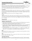
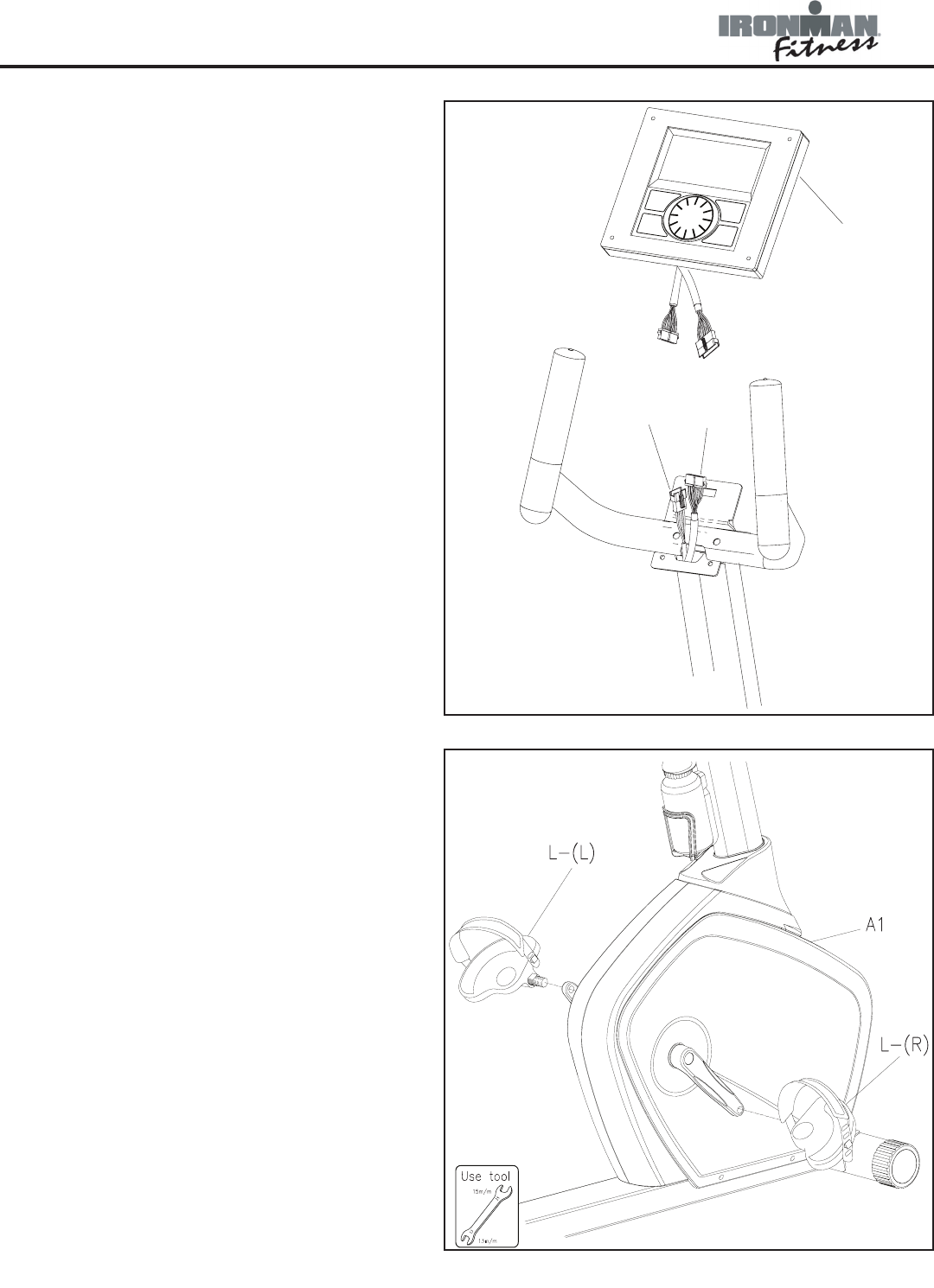
F
A26
A25
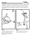
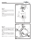
Figure 9
Step 1:
Locate console (F), and connect sensor
wires (A25 and A26) to the wires coming
from the console.
Step 2:
Gently push all of the wires into the con-
sole tube. Slide console onto the console
tube. The console will clip to the frame as
you slide it on.
Figure 9
11
Assembly
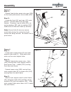
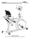
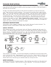
Figure 10
Step 1:
Thread the right pedal (L-R) into the right
crank area of main frame (A1). Secure in
place by turning it clockwise to tighten.
Note: Right pedal (L-R) is marked with an
“R”.
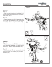
Step 2:
Thread the left pedal (L-L) into the left
crank area of main frame (A1). Secure in
place by turning it counter-clockwise to
tighten.
Note: Left Pedal (L-L) is marked with an “L”
Figure 10