


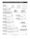
9
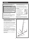
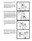
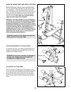
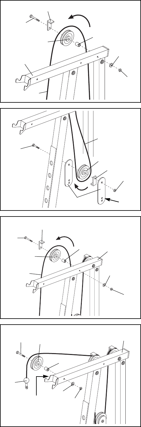
7. The Upper Cable (45) was attached to the Weight
Carriage in step 5. Wrap the Upper Cable around a
Pulley (35) in the direction shown.
Attach the Pulley (35) and a Cable Trap (61) to the
indicated hole in the Top Frame (7) with an M10 x
108mm Bolt (34), a 15.8mm Spacer (31), an M10
Washer (6) and an M10 Nylon Locknut (11). Make
sure the Cable Trap is oriented as shown, so it
will hold the Cable in place.
11
6
31
35
61
34
7
45
7
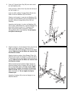
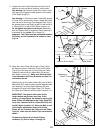
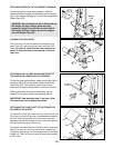
8. Note: If the Pulley Plates (62) are pre-assembled,
remove both Pulleys (35) from the Pulley Plates.
Wrap the Upper Cable (45) around a Pulley (35) in
the direction shown. Attach the Pulley and a Cable
Trap (61) to the upper holes in the two Pulley Plates
(62). Note: Make sure that both Pulley Plates are
oriented as shown, so the ends with several holes
are pointed towards the floor. Attach the Pulley with
an M10 x 48mm Bolt (55) and an M10 Nylon Locknut
(11). Make sure the Cable Trap is oriented as
shown.
61
62
35
45
55
Holes
11
8
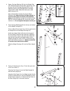
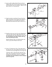
9. Wrap the Upper Cable (45) around a Pulley (35) in
the direction shown. Attach the Pulley and a Cable
Trap (61) to the indicated hole in the Top Frame (7)
with an M10 x 108mm Bolt (34), a 15.8mm Spacer
(31), an M10 Washer (6) and an M10 Nylon Locknut
(11). Make sure the Cable Trap is oriented as
shown.
11
6
31
61
34
7
35
45
9
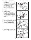
10. Route the Upper Cable (45) over a Pulley (35) in the
direction shown. Attach the Pulley to the indicated
hole in the Top Frame (7) with an M10 x 108mm Bolt
(34), a 15.8mm Spacer (31), an M10 Washer (6) and
an M10 Nylon Locknut (11). Make sure the Cable is
between the Pulley and the welded pin (not visi-
ble) on the Top Frame.
45
7
35
34
31
6
11
10
Welded
Pin