


10
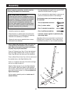
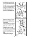
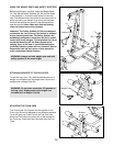
11. Locate the Lower Cable (39) and note that it has a
ball/loop on one end and a loop only on the other.
See drawing 11a. Route the end of the Lower Cable
with the loop through the cable guide on the outside
of the Right Upright (2).
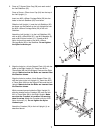
See drawing 11. Route the Lower Cable (39) around
a Pulley (35) in the direction shown. Attach the Pulley
and one end of the 2-hole Oval Support Plate (74) to
the welded tube on the Right Upright (2) with an M10
x 102mm Bolt (71) and an M10 Nylon Locknut (11).
Do not tighten the Nylon Locknut yet. Make sure
that the Support Plate is angled as shown and that it
is attached on the inside of the Upright (2).
Important: The Cable must be positioned between
the Pulley and the welded pin as shown in draw-
ing 11a.
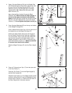
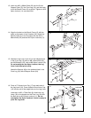
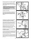
12. Wrap the Lower Cable (39) around a Pulley (35) in
the direction shown. Attach the Pulley and a Cable
Trap (61) to the lower set of holes in the two Pulley
Plates (62) with an M10 x 48mm Bolt (55) and an
M10 Nylon Locknut (11). Make sure that the Cable
Trap is between the Pulley Brackets and that it is
oriented as shown.
Slide the loop on the Lower Cable (39) onto an M10 x
68mm Bolt (33). Insert the Bolt into the indicated hole
(see drawing 11a) in the Right Stabilizer (26) and
through the 2-hole Oval Support Plate (74). Secure
the Cable and Plate with an M10 Nylon Locknut (11).
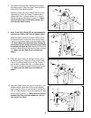
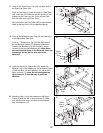
IMPORTANT: The type of cable used on the
weight bench may stretch over time. If this
occurs, you can tighten the cables by moving the
lower Pulley (35) attached to the Pulley Plate (62).
To do this, remove the M10 x 48mm Bolt (55) and
the M10 Nylon Locknut (11). Move the Bolt to one
of the higher adjustment holes in the Pulley
Plates. As you re-attach the Pulley and the Cable
Trap (61), make sure the Cable Trap is oriented as
shown.
Go back and tighten all of the M10 Nylon
Locknuts (11) used in steps 1 through 12.
2
2
11
74
61
11
39
26
55
62
11
74
33
35
1
35
71
39
11
11a
35
39
Cable Guide
Welded Tube
Adjustment
Holes
Hole for End of Cable
12
Welded Pin