


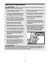
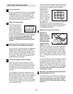
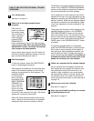
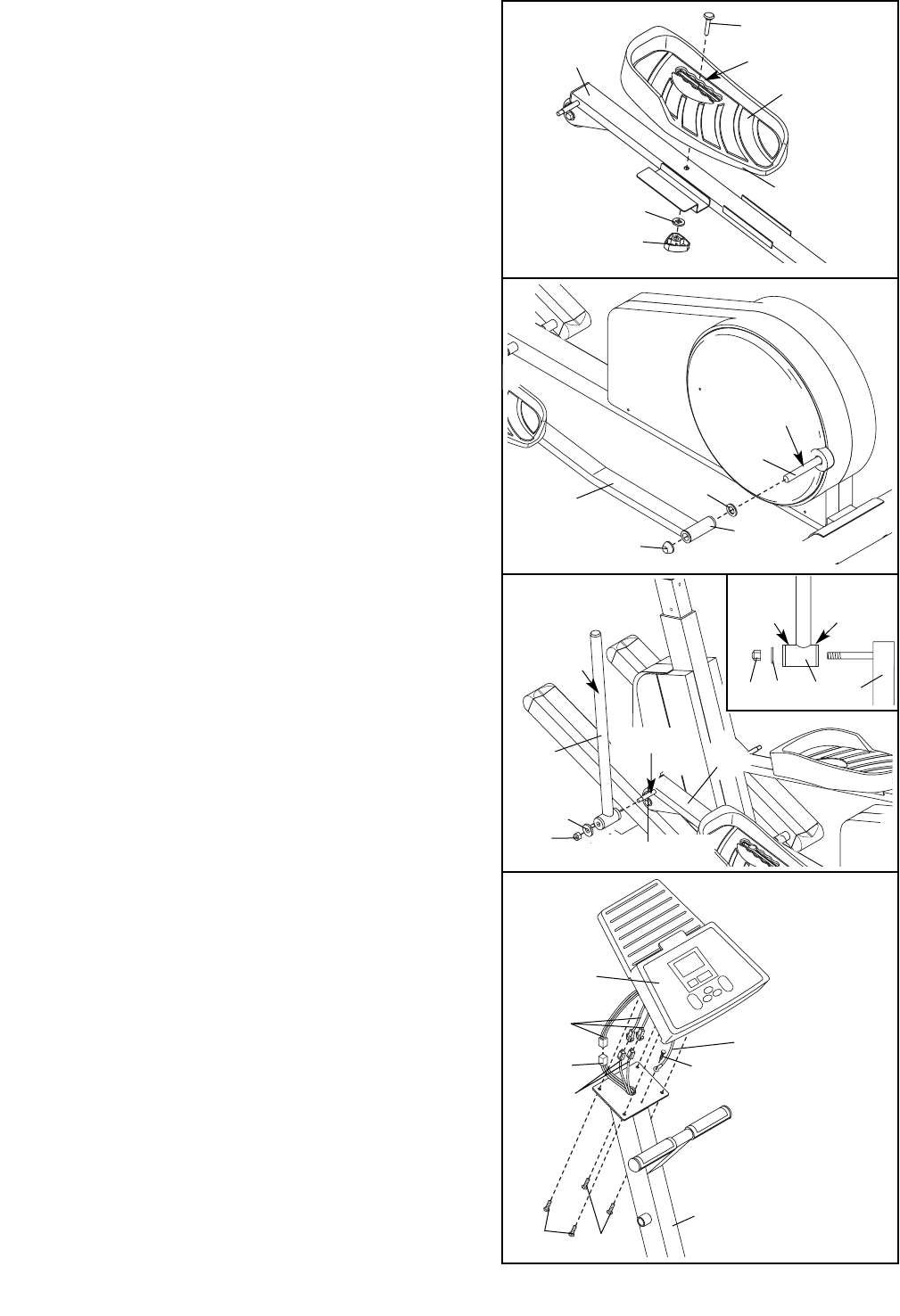
7. Apply grease to the welded bolt on the Left Pedal Arm
(3). Slide a Chrome Tube (98) and an M8 Washer (33)
onto the welded bolt. Make sure that the Chrome
Tube is turned exactly as shown in the inset draw-
ing. Tighten an M8 Nylon Locknut (80) onto the welded
bolt.
Attach the other Chrome Tube (not shown) to the Right
Pedal Arm (4) in the same way.
Apply a small amount of the included Teflon
®
lubricant
to a paper towel. Rub a thin layer of the lubricant onto
both Chrome Tubes (98).
98
33
33
Wide
Side
Narrow
Side
80
80
3
3
Grease
Lubricate
98
7
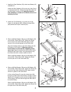
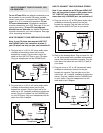
5. Identify the Left Pedal Arm (3), which has an “L” stick-
er attached to it. Identify the Left Pedal (41), which
has the letter “L” molded onto the bottom.
Insert an M10 x 65mm Carriage Bolt (43) into the cen-
ter of the slot in the Left Pedal (41) and through the
Left Pedal Arm (3). Slide an M10 Washer (94) onto the
Carriage Bolt and then tighten a Pedal Knob (103)
onto it.
Attach the Right Pedal (not shown) to the Right Pedal
Arm (not shown) in the same way.
5
43
3
41
Center Position
94
103
Open Side
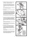
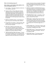
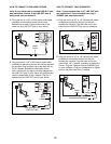
6. Apply a small amount of grease to the axle on the left
Crank Arm (6).
Slide a Plastic Pedal Spacer (11) and the Left Pedal
Arm (3) onto the axle on the left Crank Arm (6). (Note:
It may be helpful to use a rubber mallet to tap these
parts on. Do not to confuse the Left Pedal Arm with
the Right Pedal Arm [not shown]; look at the posi-
tion of the round tube to identify the Left Pedal
Arm.) Tap a 3/4” Axle Cap (61) onto the axle.
Attach the Right Pedal Arm (not shown) in the same way.
6
Grease
11
61
3
6
Round
Tube
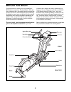
7
2
Console
Wires
Ground
Wire
99
35
35
102
87
72
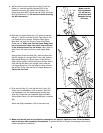
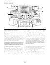
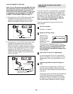
8. Remove the four Console Screws (35) from the
Console (87). Connect the Extension Harness (99)
and the Pulse Wires (102) to the corresponding con-
sole wires. The orange and black Pulse Wire
should be connected to the console wire marked
with an “R.”
Attach the ground wire to the Upright (2) with an M4 x
16mm Screw (72).
Insert all of the extra wiring into the Upright (2). Attach
the Console (87) to the Upright with the four Console
Screws (35) that you removed from the Console. Be
careful to avoid pinching the wires.
8
Make sure the
ground wire,
console wires,
and Wires (99,
102) do not get
pinched and
damaged during
this step.
Welded Bolt