


6
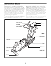
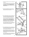
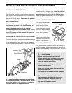
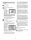
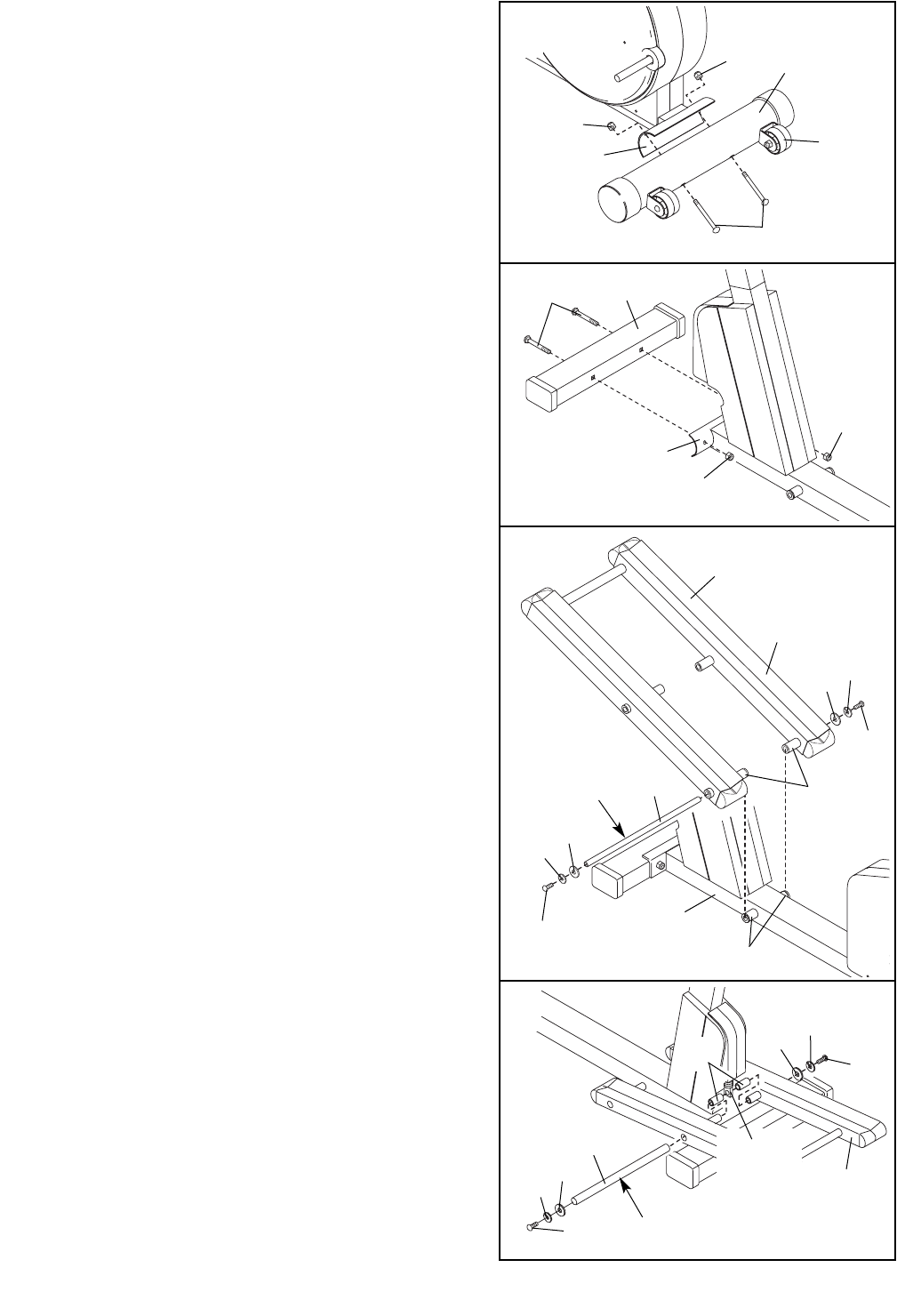
1. Identify the Rear Stabilizer (59), which has Wheels (45)
attached to it.
Attach the Rear Stabilizer (59) to the rear of the Frame
(1) with the two M10 x 105mm Carriage Bolts (60) and
two M10 Nylon Locknuts (26). Make sure that the
Rear Stabilizer is turned so the Wheels (45) are not
touching the floor.
26
1
60
45
26
59
1
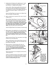
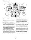
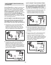
2. Attach the Front Stabilizer (14) to the front of the
Frame (1) with the two M10 x 92mm Carriage Bolts
(86) and two M10 Nylon Locknuts (26).
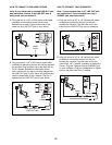
4. Slide an M8 Split Washer (58) and an M8 Washer (33)
onto an M8 x 19mm Screw (30). Tighten the Screw into
one end of the other Incline Axle (29). Apply a small
amount of grease to the Incline Axle.
Lift the Incline Ramp (5). Insert the Incline Axle (29)
through one side of the Incline Ramp, through a 57mm
Spacer (22), through the motor screw, through another
57mm Spacer (22), and then through the other side of
the Incline Ramp.
Slide an M8 Split Washer (58) and an M8 Washer (33)
onto an M8 x 19mm Screw (30). Tighten the Screw into
the open end of the Incline Axle (29).
86
14
26
26
1
2
3
5
V-shaped Groove
29
Grease
33
33
30
30
58
58
1
Tubes
Tubes
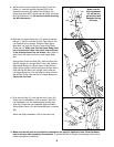
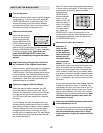
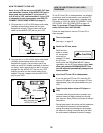
3. Slide an M8 Split Washer (58) and an M8 Washer (33)
onto an M8 x 19mm Screw (30). Tighten the Screw
into one end of an Incline Axle (29). Apply a small
amount of the included grease to the Incline Axle.
Align the indicated tubes on the Incline Ramp (5) with
the tubes on the Frame (1). Make sure that the
Incline Ramp is turned so the V-shaped grooves
are on top. Insert the Incline Axle (29) into the Incline
Ramp and the Frame. Note: It may be helpful to tap
the Incline Axle with a rubber mallet to insert it.
Slide an M8 Split Washer (58) and an M8 Washer (33)
onto an M8 x 19mm Screw (30). Tighten the Screw
into the open end of the Incline Axle (29).
5
29
30
30
58
58
33
33
Grease
22
Motor
Screw
4