


16
ASSEMBLY GUIDE
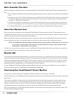
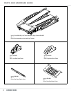
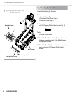
ASSEMBLY PROCESS
Wiring Harness
Step 2: Installing Console/Handlebar Assembly
Locate the following for this step:
Parts:
• Assembly from Step 1
• Console/Handlebar Assembly
• Upright to Console Junction Covers
Hardware:
• 5/16 x 1 inch Button Head Screws (Qty. 8)
• 5/16 inch Flat Washers (Qty. 8)
Tools:
• Hex Key
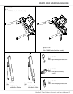
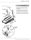
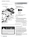
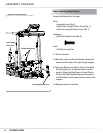
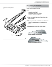
2-1 C ut the zip tie securing the wiring harness to
the top of the Right Upright Support and place
Junction Covers on top of Uprights.
2-2 Connect the wiring harness from the top of the
Right Upright Support to the connector in the right
handrail of the Console/Handlebar Assembly,
matching the pin connectors.
2-3 Slide Console/Handlebar Assembly mounting
bracket into Left and Right Upright Supports.
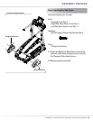
2-4 Fasten Console/Handlebar Assembly onto Right
and Left Upright Supports using 3 Button Head
screws, and 3 flat washers on the inside of each
support and 1 Button Head screw and 1 flat
washer on the front of each support.
2-5 Tighten all screws securely.
NOTE: Tighten the front screws securely first and
then the 3 inside screws.
Figure 2: Installing Console/Handlebar Assembly
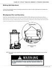
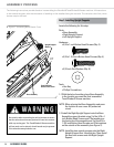
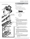
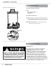
Use caution when connecting the wiring harness to ensure
that the wires do not become pinched or come into contact
with any moving part. The TreadClimber® fitness machine
will not work and an electric shock hazard may be present
if the wires become pinched.
7 ! 2 . ) . '
! 4 4 % . 4 ) / .
$ ! . ' % 2
)--%$)!4%!#4)/.2%15)2%$
# ! 5 4 ) / .
IMPORTANT!
MAKE SURE THAT
THE CABLES DO NOT
BECOME PINCHED
BETWEEN THE
CONSOLE AND THE
RIGHT UPRIGHT
ASSEMBLY BEFORE
PROCEEDING.
Right Upright Support
Left Upright Support
Console/Handlebar Assembly
Button Head Screws
Flat Washers
Cut Zip Tie Securing
Wiring Harness
Upright to Console
Junstion Cover
Upright to Console Junstion
Cover