


A-4
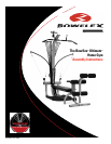
Assembling Your Bowflex
®
Ultimate
™
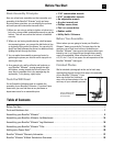
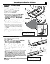
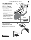
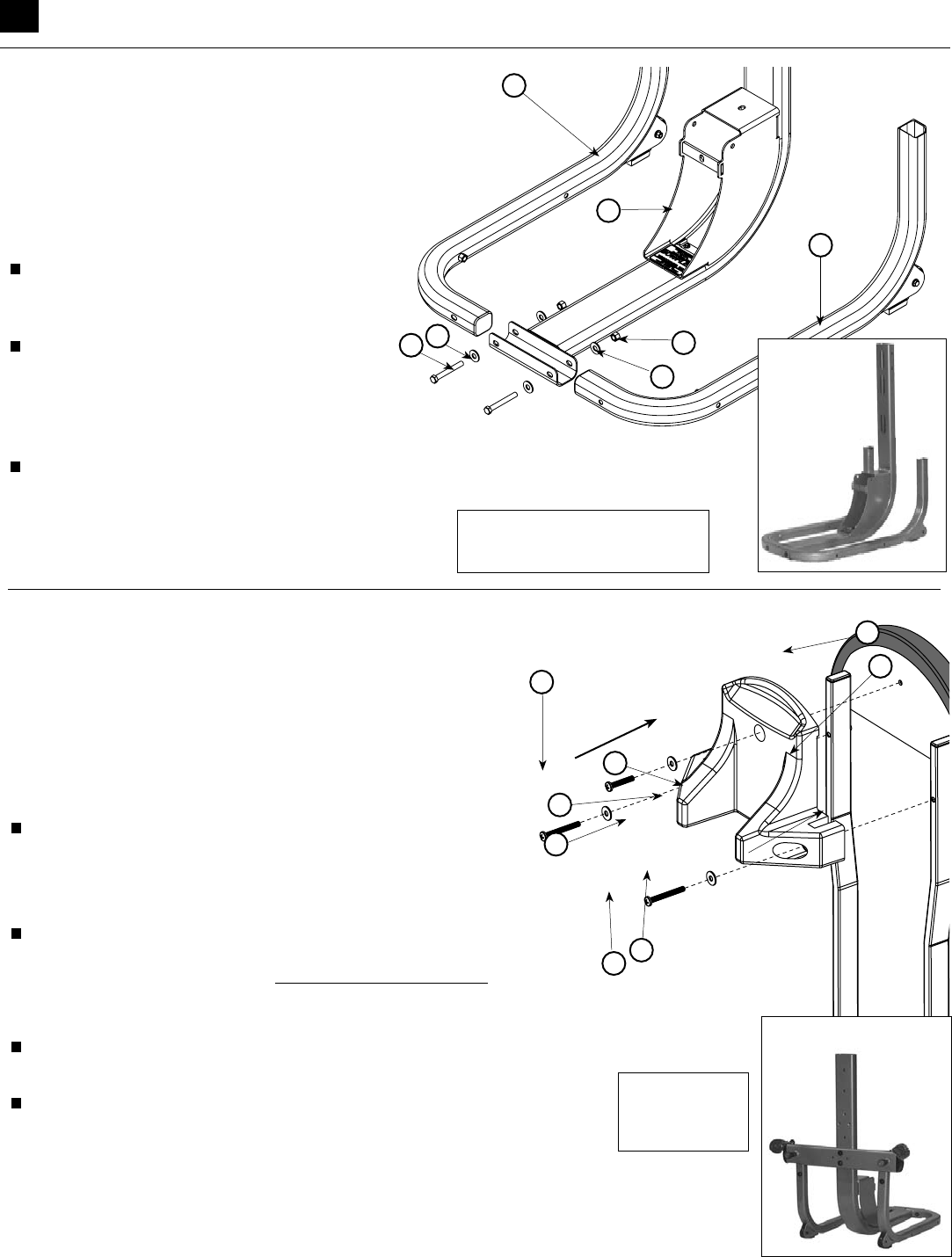
Step 2: ADJUSTABLE PULLEY SYSTEM
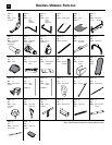
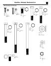
Locate the following for this step:
• Adjustable Pulley System (Item #6)
• Two (2) Adjustable Pulley System bolt spacers
(Item #7, twist tied to Adjustable Pulley System)
• Two (2) 3/8”X2-1/2” bolts (Item #49)
• Two (2) 3/8”X3/4” bolts (Item #46)
• Four (4) 3/8” washers (Item #54)
• Two (2) Adjustable Pulley System lock knobs (Item #8)
Remove twist ties from bolt spacers and slide Adjustable
Pulley System (Item #6) into main frame uprights as
shown in Figure B.
Note: The side with two large holes faces away from the machine.
Insert both 3/8”X2-1/2” bolts (Item #49) with 3/8” washers
(Item #54) into chest slide spacers and hand tighten into the back
of lower lat tower (Item #1) (NOTE: DO NOT OVERTIGHTEN)
Note: Inserting the top bolt first will help you align the parts.
Hand tighten the 3/8”X3/4” bolts (Item #46) with 3/8” washers
(Item #54) into the uprights of the main frame (Items #2&3).
Make sure all the holes are properly aligned and screw the two
spring-loaded locking knob assemblies (Item #8) into the back side
of the Adjustable Pulley System as shown in figure B. Tighten the
locking knobs to the Adjustable Pulley System with an adjustable wrench.
Note: Do not unwrap the two pulley assemblies that are attached
to the Adjustable Pulley System at this time.
• Securely tighten all bolts that have been placed on the unit up to this stage.
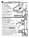
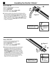
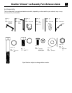
Step 1: LOWER MAIN FRAME ASSEMBLY
Locate the following for this step:
• Lower lat tower (Item #1)
• Left main frame (Item #2)
• Right main frame (Item #3)
• Two (2) 3/8”X3” bolts (Item #51)
• Four (4) 3/8” washers (Item #54)
• Two (2) 3/8” nylon lock nuts (Item #57)
Place the left main frame (Item #2) into the
saddle bracket of the lower lat tower (Item
#1) as shown in Figure A.
Insert a 3/8”X3” bolt (Item #51) with a
washer on it through the appropriate holes,
place a 3/8” washer (Item #54) and then a
3/8” nylon lock nut (Item #57) on the bolt,
hand tighten at this time.
Place the mating right hand side of the main
frame (Item #3) next to the left side of the
frame in the lower lat tower saddle bracket
(Item #1) and repeat step above.
Note: Hand tighten all bolts at this stage.
Figure A
Figure B
1
2
3
54
54
51
1
6
49
46
54
7
8
54
57
Unit appears like
this following this
assembly step
Unit appears like this
following this assembly step
Components for this step
are in Box 2 & Box 4
Components
for this step
are in Box 4