11
“ASSEMBLY INSTRUCTIONS”
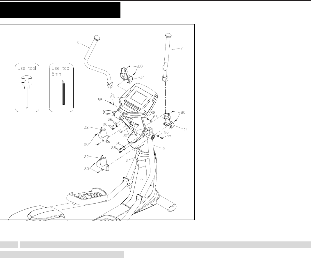
STEP 16 – Upper Handlebar Assembly
NOTE: For shipping purpose, the Button Head Bolts (M8xp1.25x16mm)(88) and Lock Washers (M8)(66) are attached
on the Left and Right Action Handlebar (6, 7).
a. Remove the 8x Button Head Bolts (M8xp1.25x16mm) (88) and 8 x Lock Washers (M8) (66) from the Left and
Right Action Handlebar (6, 7).
b. Following the assembly drawing, insert the Right Action Handlebar (7) onto the Right Pivoting Arm (9) and secure
with the 4x Button Head Bolts (M8xp1.25x16mm)(88) and 4 x Lock Washers (M8)(66).
c. Repeat the above procedure to insert and secure the Left Action Handlebar (6) onto the Left Pivoting Arm (8).
STEP 17 – Action Arm Cover Assembly
a. Place the Front Action Arm Cover (31) and the Back Action Arm Cover (32) over the Right Pivoting Arm (9).
b. Fasten the Covers together with the 4 x Round Head Screws (M5xp0.8x15mm) (80).
c. Repeat the above procedure to place the Front Action Arm Cover (31) and the Back Action Arm Cover (32) at
both sides of the Left Pivoting Arm (8).
For the final step, make sure all the bolts and nuts are tighten securely before using.


