


page 9
COMMERCIAL PRODUCTS DIVISION
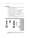
HARDWARE KIT
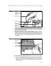
After unpacking the treadmill, open the hardware kit and make sure that you have
the following items shown in Diagram 2.
❑ (A) twelve 1-inch buttonhead hex screws
❑ (B) twelve flat stainless steel washers — place on 1-inch buttonhead hex screws
❑ (C) four 1/2-inch flat head hex screws — attach to upper handrails
❑ (D) four 3 1/4-inch socket head screws — install upright supports
❑ (E) four flat black washers — place on 3 1/4-inch socket head screws
❑ (F) four barrel spacers — place on 3 1/4-inch socket head screws after washers
❑ (G) 5/32-inch hex key — attach handrails to display frame
❑ (H) 3/16-inch hex key — attach hood, mount upright supports, attach display
and handrails to base frame
❑ (J) 1/4-inch hex key — attach upright supports to base mounting brackets
❑ (K) 5/16-inch hex key — adjust running belt
Diagram 2
Hardware kit (not shown to scale).
AC
D
B
E
F
G
H
J
K
Note: After assembling the treadmill, be sure to store the hex keys in a secure
place. The tools are used for specific maintenance procedures that are described
in this manual.