


page 15
COMMERCIAL PRODUCTS DIVISION
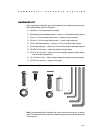
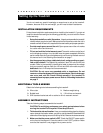
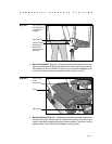
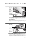
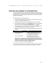
8. Secure the upright support. Diagram 11, #1. Obtain two screws (D), washers
(E) and barrel spacers (F) from the Hardware kit. Place a washer and barrel
sleeve on each bolt and insert the fasteners through the side of the upright
support and into the base mounts. Secure the upright support using the 1/4-inch
hex key. See Diagram 11, #3.
Important: Do not securely tighten the screws until after the unit has been fully
assembled. Make sure that the bolt and spacer do not pinch the cable.
9. Insert the two bolts removed in step 5a, and finger tighten. Diagram 11, #2.
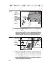
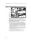
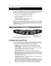
10. Secure the display console to the upright supports. Diagram 12. Align the
display console with the right side upright support mounts. Insert two 1-inch
screws (A) with washers (B) and finger tighten. Fully tighten the screws using
the hex key provided. Do the same for the opposite upright support. See inset
in Diagram 12.
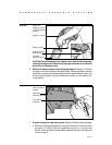
Diagram 11
Secure the right
upright support.
Tighten so that
the upright is
secure, but
leave room for
adjustments.
Right upright
support
Front panel
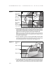
Diagram 12
Secure the
display console.
Tighten the
screws, but
leave room for
adjustments.
1-inch screws (A)
with washers (B)
Display console
Screws (D),
washers (E),
and barrel
spacers (F)
1
2
3