


Page 14
USA
R
USA
R
USA
R
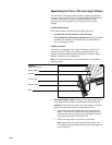
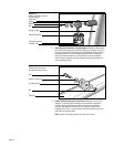
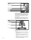
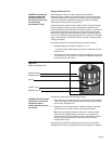
Diagram 16
Location of magnet and reed switch.
Left stair arm
Resistance cylinder
Base column support
Magnet
Reed switch
10. Check Operation of Electronics. (Diagram 16) Make sure that the spacing
between the magnet on the left stair arm and the reed switch on the rear
short column is correct. If the spacing is incorrect, the electronic console
display will not operate properly. The distance between the magnet and the
reed switch should be about 1/8 inch (.3 centimeters). If the spacing is not
correct, adjust the spacing by moving the reed switch in or out of the
column with your fingers.
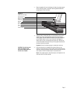
11. Set the Resistance. Adjust the stair arm resistance by turning the top of
the resistance cylinder until the triangle on the resistance cylinder points to
the “2” on the adjustment knob. Do the same for the other stair arm. Make
sure that the resistance on both stair arms is at the same setting.
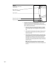
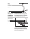
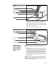
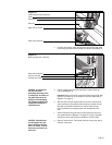
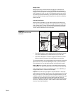
Diagram 17
Align stair arms with label (718e only).
12. Install Rope—718e only. (Diagrams 17, 18 and 19) To properly install the
red rope (set aside in step 2), get a marker (pen or pencil) and take the
following steps:
a. Feed the rope up through the right stair arm mount. (Determine right
and left while standing behind the rear crossbar and facing toward the
electronic console.)
b. Move both stair arms so that the
top
of the stair arms line up with the
red box located on the Precor label. See Diagram 17. Have an
assistant hold the stair arms in place while you route the rope through
the pulley.
Note: It may be easier to install the guide rope if the climber is placed
on its right hand side on the floor. This will expose the underside of
the stair arms and provide easier accessibility.
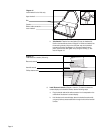
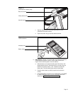
Precor label red box
Stair arm footpad
Rope
Gap 1/8" to 1/4"
(.3 to .6 centimeters)
Rear crossbar