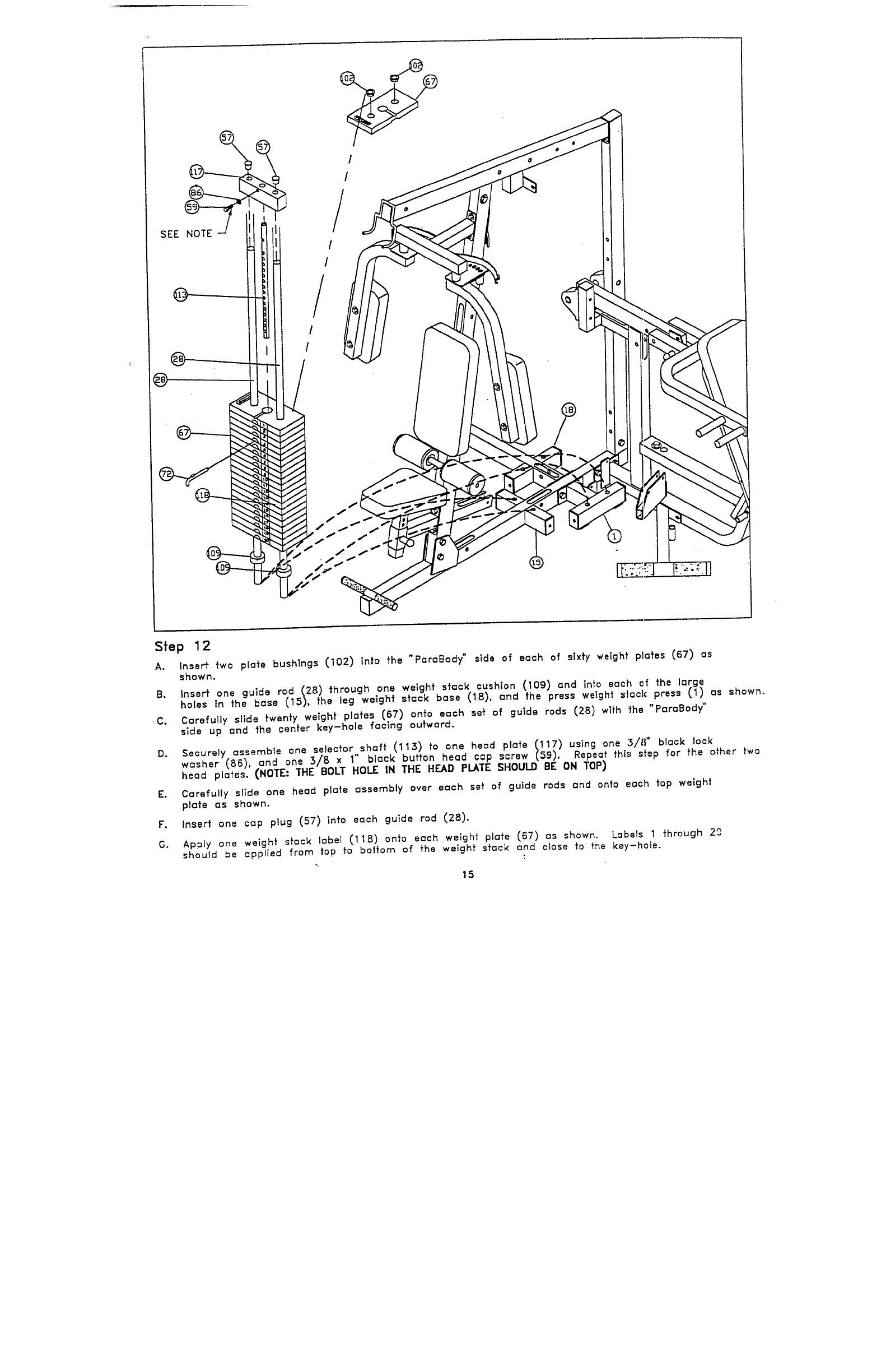
SEE NOTE
Step 1 2
A.
Insert two plate bushings (102) into the "ParaBody" side of each of sixty weight plates (67)
shown.
B. Insert one guide rod (28) through one weight stack cushion (109) and into each ef the large
holes in the base (15), the leg weight stack base (18), and the press weight stack press (1) as
C.
Carefully slide twenty weight plates (67) onto each set of guide rods (28) wlfh the "ParaBody"
side up and the center key-hole facing outward.
D.
Securely assembe one selector,shaft (113) to one head plate (117) using one 5/8" block
washer (86), and .one 3/8 x 1’ black button head cap screw (59). Repeat this step for the other two
head plates. (NOTE: THE BOLT HOLE IN THE HEAD PLATE SHOULD BE ON TOP)
E.
Carefully slide one head plate assembly over each set of guide rods and onto each top weight
plate as shown.
F.
Insert one cap plug (57) into each guide rod (28).
G.
Apply one weight ~sfock label (118) onto each weight plate (67) as shown. Lc~bels 1 through
should be applied from top to bottom of the weight stock and close to f~’,e key-hole.
.-,
15


