


49
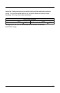
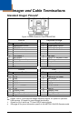
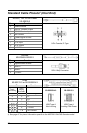
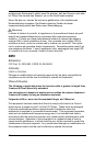
Imager and Cable Terminations
Standard Imager Pinouts
‡
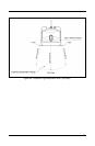
Figure 34. Back/Connector View of the MS7580
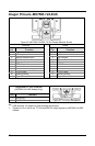
RS232
Keyboard Wedge
Pin
Function Pin Function
1
Signal/Power Ground
1
Signal/Power Ground
2
CTS/DTR Input
2
Tied to Pin 3 in Cable
3
RS232 Receive Input
3
Tied to Pin 2 in Cable
4
No Connect
4
PC Data
5
No Connect
5
PC Clock
6
RTS Output
6
KB Clock
7
No Connect
7
+5VDC PC Keyboard Power
8 RS232 Transmit Output 8 KB Data
9 Adapter Power 9 Adapter Power
10
Shield Ground
10
Shield Ground
SHELL
Signal/Power Ground
SHELL
Signal/Power Ground
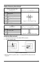
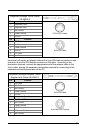
RS485
USB
Pin
Function
Pin
Function
1
Signal/Power Ground
1
Signal/Power Ground
2
CTS
2
Tied to Pin 4 in Cable
3
RXD
3
No Connect
4
PC Data
4
Tied to Pin 2 in Cable
5
PC Clock
5
No Connect
6 KB Clock 6 USB D+
7 Keyboard/USB Power 7 +5VDC USB Power
8 TXD 8 USB D-
9 Adapter Power 9 Adapter Power
10
Shield Ground
10
Shield Ground
SHELL Signal/Power Ground
SHELL Signal/Power Ground
RS485, RS232, and Keyboard Wedge interfaces require 12V power for operation.
Signals on Pin 6 and 8 are TTL level RS232 output signals.
USB requires 12V power for pass-through functionality.
‡ See page 46 for pinout information specific to the MS7580-124-EAS Genesis model.