16
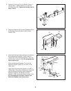
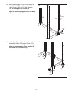
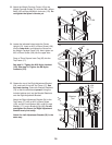
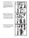
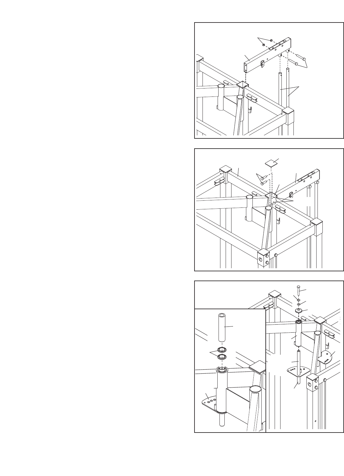
23. Attach the Weight Carriage Frame (18) to the
W
eight Carriage Guides (21) with two M8 x 40mm
Bolts (136) and two M8 Nylon Locknuts (170). Do
n
ot tighten the Nylon Locknuts yet.
23
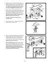
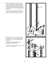
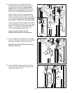
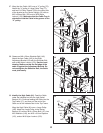
24. Locate the indicated holes inside the Center
Upright (13). Insert an M10 x 25mm Screw (128)
into the lower hole, and tighten the Screw into
the Weight Carriage Frame (18). Next, tighten an
M10 x 25mm Screw (128) into the upper hole.
Press a 75mm Square Inner Cap (95) into the
Top Frame (17).
See step 21. Tighten the M10 Nylon Locknut
(153). See step 23. Tighten the M8 Nylon
Locknuts (170).
24
18
18
13
95
128
17
136
1
70
2
1
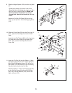
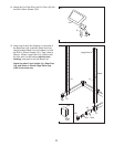
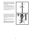
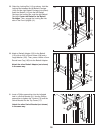
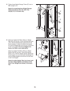
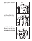
25. Grease the top of the Right Adjustment Bracket
(24), and insert it into the Top Frame (17). See
the inset drawing. Orient two Bracket Retainers
(73) so that the teeth bend
upward. Using the
included retainer tool, tap the Bracket Retainers
onto the
Right
Adjustment Bracket.
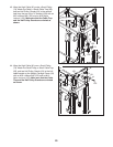
Attach the Right Adjustment Bracket (24) to the
T
op Frame (17) with an M10 x 30mm Screw
(134), an M10 Lock W
asher (86), an M10 Large
Washer (171), and a Bushing Cap (88).
Do not
overtighten the Screw; the Right Adjustment
Bracket must pivot easily.
Attach the Left Adjustment Bracket (25) in the
same way.
25
134
171
86
24
25
Grease
17
24
88
73
Retainer
Tool
Holes


