


9
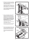
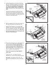
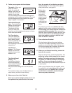
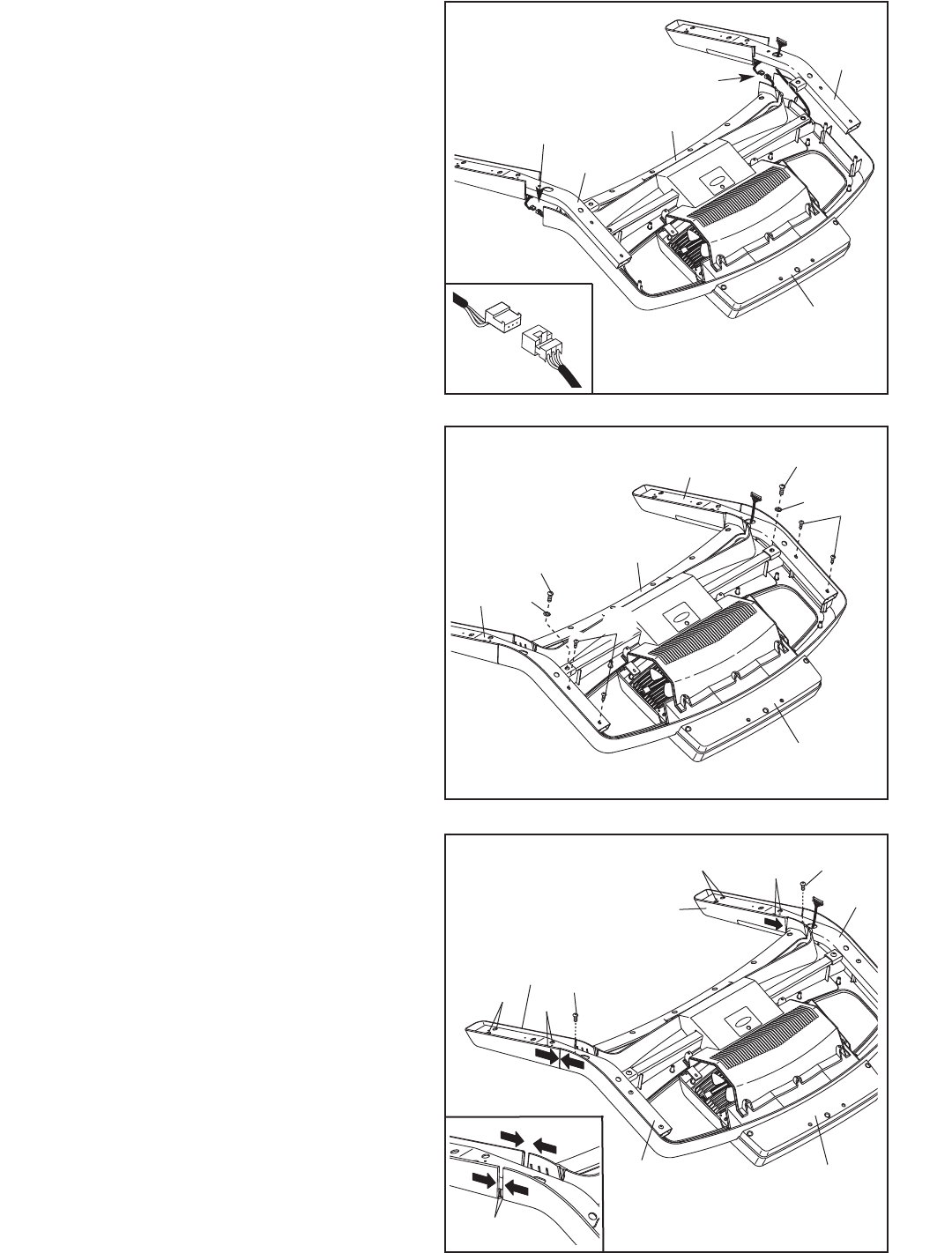
9. Insert the speed wires and the incline wires into
the area at the ends of the Pulse Bar (103).
Attach the Left Handrail (101) and the Right
Handrail (105) to the console assembly with four
#8 x 1/2" Screws (2), two 3/8" x 3/4" Patch Bolts
(8), and two 3/8" Star Washers (10). Make sure
no wires are pinched. Do not fully tighten the
Screws or Patch Bolts yet.
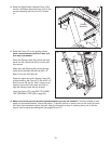
10. Press the Left Handrail Cover (100) against the
console assembly. See the inset drawing.
Align the lip on the Left Handrail Cover with the
lip on the console assembly. Make sure no
wires are pinched. Then, fully tighten the four
#8 x 1/2" Screws (2) in the Left Handrail (101).
Note: The Screws are preattached.
Repeat this step with the Right Handrail
Cover (107).
Tighten two 1/4" x 1/2" Bolts (3) into the
Handrails (101, 105) and the console assembly.
See step 9. Fully tighten the four #8 x 1/2"
Screws (2) and the two 3/8" x 3/4" Patch Bolts
(8).
10
Console
Assembly
3
3
100
107
2
2
2
2
Lips
101
105
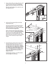
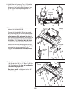
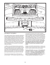
8. Locate the speed wire in the end of the Pulse
Bar (103). Connect the speed wire in the Right
Handrail (105) to the speed wire in the Pulse
B
ar. See the inset drawing. The connectors
should slide together easily and snap into
p
lace. If they do not, turn one connector and try
again.
Locate the the incline wire in the end of the
Pulse Bar (103). Hold the Left Handrail (101)
near the console assembly. Connect the incline
wire in the Left Handrail to the incline wire in the
Pulse Bar as described above.
8
105
101
103
103
Console
Assembly
Speed Wires
Incline
W
ires
Console
Assembly
2
10
8
105
8
10
101
9
2