9
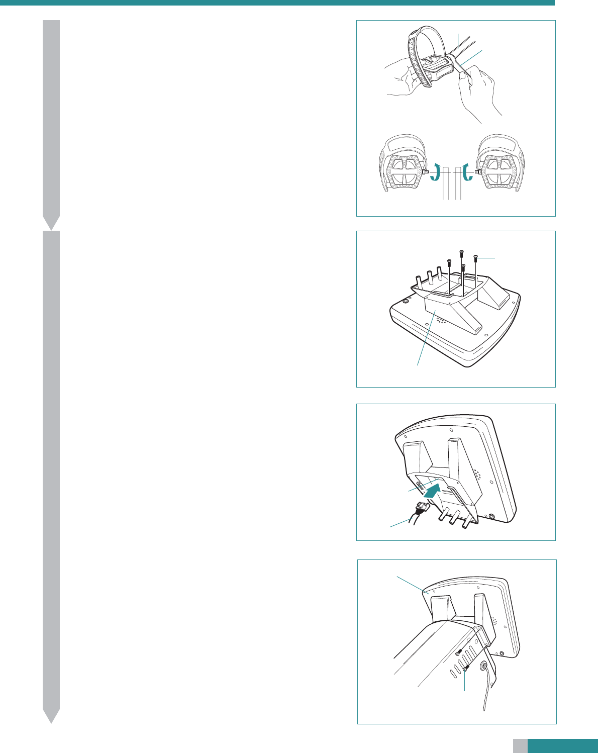
Attach the pedals.
• Use the No.15 end of the spanner to attach the pedals firmly to the
cranks.
• The right and left pedals are different, so be sure to check for R and
L marks.
•Tighten the right pedal by turning clockwise, and the left pedal by
turning counterclockwise.
Caution: If the pedals are not attached firmly enough to the
crank, they can cause an irritating noise. Be sure to
attach them firmly.
6
7
Attach the control unit base to control unit.
Reference: Units of weight, and units of pedaling resistance can
be changed using the select switches at the back of the
control unit. The settings before shipping are as fol-
lows; units of weight: lbs, and units of pedaling resis-
tance unit: kg·m.
For information on the various settings which can be
carried out with these switches, refer to the Reference
section on page 48.
• Attach the control unit base to the back of the control unit as illus-
trated and fasten the base by the 4 screws.
Crank
No.15 end of the
spanner
Left
Right
Front
• Insert the cable connector coming out of the main unit into the cable
inlet at the back of the control unit, until it clicks into place.
Caution: Ensure that the connector is completely connected. If
the connection is insufficient the unit will not work.
• Place the control unit on the main unit as illustrated and fasten it by
the 4 screws.
Cable inlet
Cable connector
Screw
Control unit base
Control unit
Screw


