


CC-TR100
98
CC-TR100
E
D
K
D
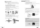
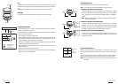
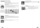
NOTE:
When the crank is spinning, the center of the magnet
M
should pass in front of the
sensor
G
marking line. The distance between the sensor and the magnet
M
should
be within 5 mm. After adjusting the magnet and sensor, secure tightly with nylon ties.
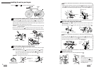
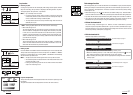
3
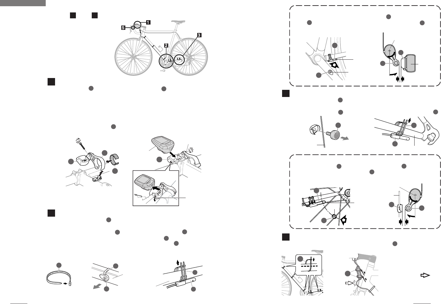
Mount the wheel magnet and speed sensor
• Mount the wheel magnet
L
to a spoke on the rear wheel so that the magnet surface
faces the sensor.
• Secure the speed sensor
F
(long wire) onto the left chain stay with nylon ties
J
.
L
J
F
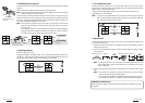
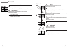
NOTE:
The center of the magnet
L
should pass in front of the sensor
F
marking line. The
distance between the sensor and the magnet
L
should be no more than 5 mm. After
adjusting the magnet and sensor, secure them tightly with nylon ties.
4
Secure the sensor wire
Secure the wire onto the frame using the supplied nylon ties
J
.
J
G
M
M
G
5 mm
F
L
L
F
5 mm
Center
Marked line
Crank arm
Adjust
Left chain stay
Rear wheel spoke
Sensor Side
Left chainstay
Center
Marked
sensor
line
Adjust
Left chainstay
Rear wheel
spoke
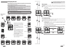
CAUTION !:
Allow enough wire clearance in
the area marked with
to in-
sure you can turn the handlebars
all the way from side to side with-
out pulling the wire.
J
The smooth side of the zip
tie should be on the outside
Inward side of the
left crank arm
J
J
M
J
G
Left chain stay
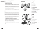
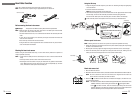
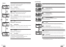
Installing the unit on your bicycle
Follow steps
1
through
5
to mount the TR100 on your bicycle.
1
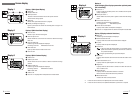
Mount the bracket and HR receiver, and then attach the main unit
• Mount the bracket
E
to the handlebar, using the rubber pad
K
as a spacer. Adjust the
bracket to a position that provides good visibility and securely fasten it with the screw.
Adjust the angle of the bracket and receiver so that each provides good visibility with the
main unit attached. Then, tighten all screws securely.
CAUTION !: Check periodically that the receiver screw is not loose in order to prevent the
receiver from falling.
• Attach the main unit to receiver
D
by sliding it in from the front until a click is heard.
To remove the main unit, push it forward while lowering the lever on the side of the receiver.
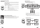
2
Mount the cadence magnet and cadence sensor
• Mount the cadence magnet
M
to the inner side of the left crank so that the magnet
surface faces the sensor.
NOTE: The center of the magnet
L
should pass in front of the sensor
F
marking
line. The distance between the sensor and the magnet
L
should be no more
than 5 mm. After adjusting the magnet and cadence sensor
G
, (short wire),
secure them tightly with nylon ties.
CAUTION !: The nylon ties can only be used once, please install with care.
Sensor side
Lever
HR receiver screw
Main unit
Remove