Commander GP User Guide
Issue code: gpxu2
Menu 0 Parameters D-15
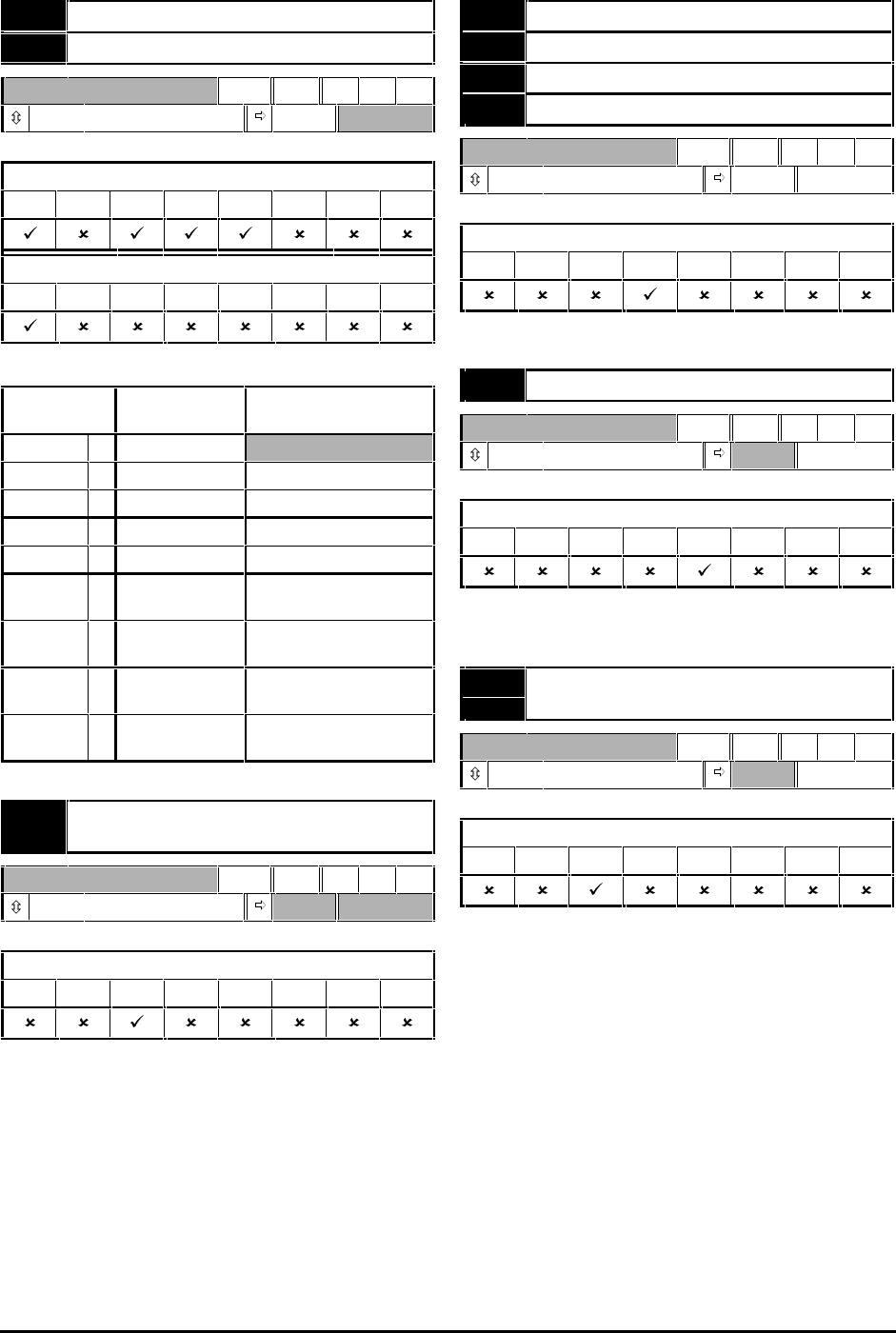
0.24 Analog input 1 mode selector
0.25 Analog input 2 mode selector
RW Txt P
(See below) VOLt
0.24 – Applicable to Macros...
01234567
0.25 – Applicable to Macros...
01234567
Set the required mode as follows:
Setting Input signal When current
signal ≤≤3mA...
VOLt 0 0V to 10V
0–20 1 0 to 20mA Signal treated as zero
20–0 2 20mA to 0 Signal treated as zero
4–20.tr 3 4mA to 20mA Drive trips
20–4.tr 4 20mA to 4mA Drive trips
4–20.Lo 5 4mA to 20mA Drive runs at minimum
or low speed
20–4.Lo 6 20mA to 4mA Drive runs at minimum
or low speed
4–20.Pr 7 4mA to 20mA Drive runs at previous
speed
20–4.Pr 8 20mA to 4mA Drive runs at previous
speed
0.25 Motorized potentiometer reset
indicator
RO Bit
0 ~ 1
Applicable to Macros...
01234567
When 0.25 is set at 1, this indicates that the
motorized potentiometer output is reset to 0%.
The motorized potentiometer is reset when the
RESET contact is closed (terminal 25) (only when
Macro 2 is enabled).
0.25 Preset reference 1
0.26 Preset reference 2
0.27 Preset reference 3
0.28 Preset reference 4
RW Bi
±1000 0Hz
Applicable to Macros...
0123
567
Enter the required values.
0.25 Analog reference 1
RO Bi
±1000
Hz
Applicable to Macros...
0123
567
0.25 indicates the value of the torque reference
applied to terminals 5 and 6 of the signal connector.
0.26 Motorized potentiometer
output indicator
RO Bi S
±100
%
Applicable to Macros...
0123
567
0.26 indicates the value of the output of the
motorized potentiometer as a percentage of the
maximum value.


