Commander GP User Guide
Issue code: gpxu2
Menu 0 Parameters D-9
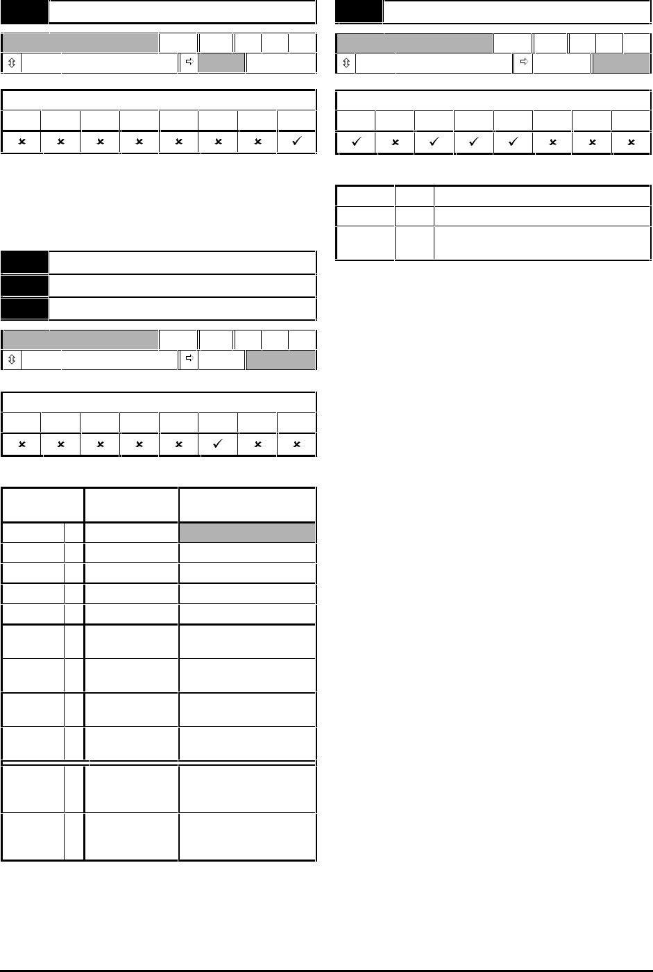
0.14 Motor current magnitude
RO Uni P
0 ~ I
max
A
Applicable to Macros...
01234567
0.14 indicates the measured value of phase current
in the motor; this is the vector sum of the active and
magnetizing currents.
I
MAX
= FLC x 150%
0.14 Analog input 1 mode selector
0.15 Analog input 2 mode selector
0.16 Analog input 3 mode selector
RW Txt P
(See below) VOLt
Applicable to Macros...
01234567
Set the required mode as follows:
Setting Input signal When current
signal ≤≤3mA...
VOLt 0 0V to 10V
0–20 1 0 to 20mA Signal treated as zero
20–0 2 20mA to 0 Signal treated as zero
4–20.tr 3 4mA to 20mA Drive trips
20–4.tr 4 20mA to 4mA Drive trips
4–20.Lo 5 4mA to 20mA Drive runs at minimum
or low speed
20–4.Lo 6 20mA to 4mA Drive runs at minimum
or low speed
4–20.Pr 7 4mA to 20mA Drive runs at previous
speed
20–4.Pr 8 20mA to 4mA Drive runs at previous
speed
th.SC 9 Thermistor
(analog input 3
only)
Drive trips if short-
circuit detected
th 10 Thermistor
(analog input 3
only)
(No short-circuit
detection)
0.15 Ramp mode selector
RW Txt
(See below) Stnd.Ct
Applicable to Macros...
0123
567
Select the required ramp mode as follows:
Stnd.Hd (0)
Standard ramp with ramp hold
FASt (1)
Fast ramp
Stnd.Ct (2)
Standard ramp with proportional
control
Set 0.15 Ramp mode selector for the required means
of controlling regenerated energy. Regeneration
arises when the Drive is braking the motor. This
occurs when the Drive decelerates the motor, or
prevents the speed of the motor from being
increased as a result of mechanical influences.
Regeneration causes the
DC-bus voltage to be
increased. The settings for 0.15 determine the braking
action in relation to a
DC-bus threshold level known as
the standard ramp voltage which is fixed at 750V.
0.15 set at Stnd.Hd (0)
Standard hold
If motor regeneration causes the DC-bus voltage to
reach the standard ramp voltage, the braking is
interrupted until the
DC-bus voltage reduces
sufficiently. Braking then continues until the next
time the
DC-bus voltage reaches its limit, resulting in
maximum braking occurring in steps.
0.15 set at FASt (1)
Fast ramp
This setting gives continuous deceleration under
maximum braking conditions. This can give faster
deceleration than the Stnd.Hd setting with the result
that the regenerated power is greater. A braking
resistor is normally required in order to prevent the
DC-
bus voltage from reaching the trip level.
0.15 set at Stnd.Ct (2)
Standard controlled
(default setting)
Deceleration is smoother than with the Stnd.Hd
setting. The deceleration is controlled by a current
controller in the Drive in order to maintain the
DC bus at or below the standard ramp voltage
(750V). When necessary, this extends the
deceleration time. Do not use this setting when a
braking resistor is connected to the Drive.


