85
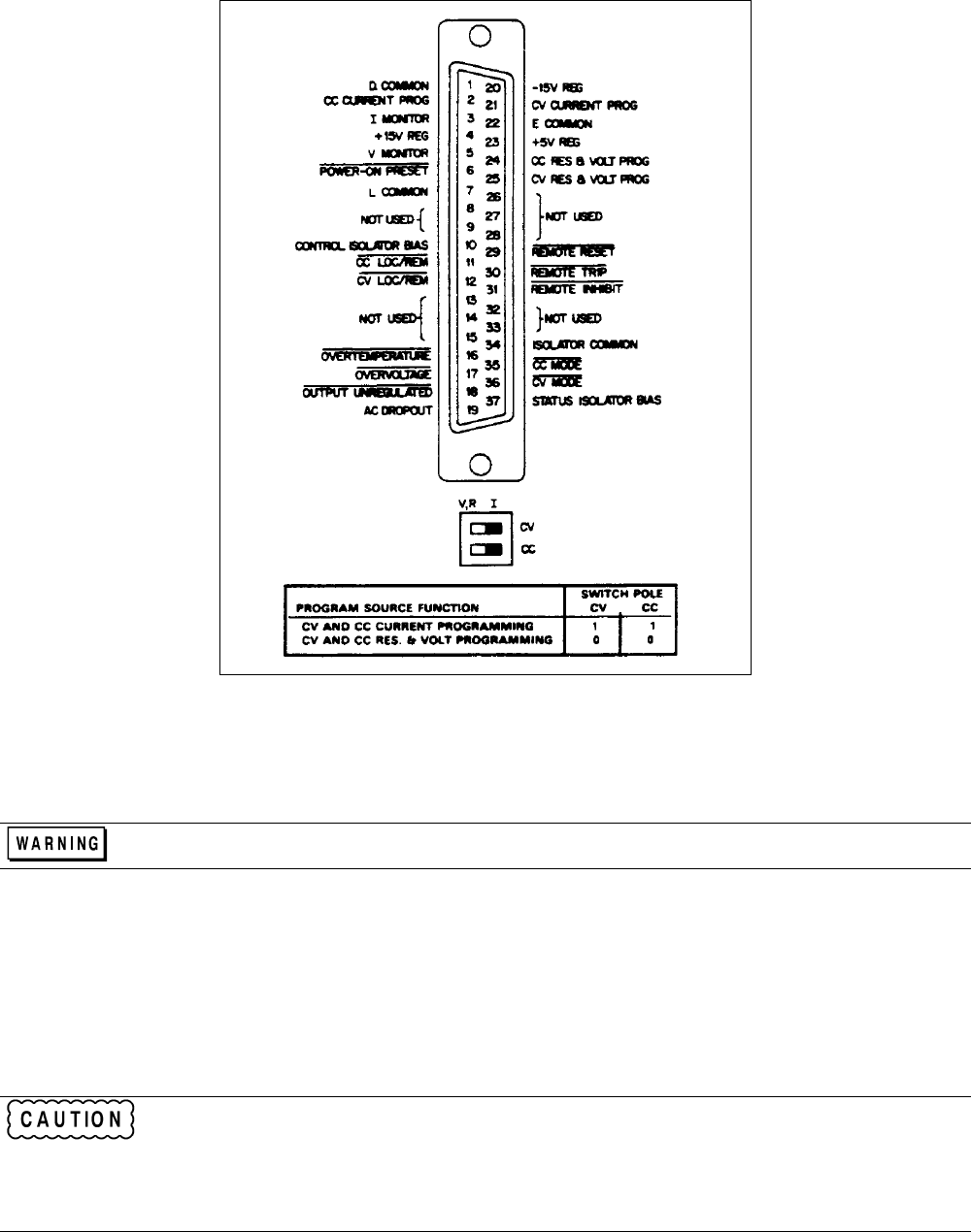
Figure A-2. 002 Option Rear Panel Connector J3 and Switches A1 and A2.
Local/Remote Programming
When switching to local/ control, remember to set Front-Panel Voltage and Current Control to safe levels.
Local Programming (Figure A-3). The supply can be switched back and forth between remote and local programming
while initially checking out a remote programming circuit. For proper operation of local programming, the user must
supply the bias voltage (CONTROL ISOLATOR BIAS). The Control Isolator Bias voltage can range from +4.75V to
+ 16V depending upon the user's interface circuits. Refer to Specifications Table A-1. For local programming, take the
Control Isolator Bias common and connect it to both of the LOC/REM terminals, and position mode switch as indicated in
Operation.
Although CONTROL ISOLATOR BIAS can be + 4. 75V to + 16V, a supply voltage of more than 7V
may damage the relays. Therefore, if CONTROL ISOLATOR BIAS exceeds 7V it is necessary to use a
resistor in series with each of the LOC/REM terminals. Figure A-4 provides a graph from which the
proper series resistance value can be determined. Note that the tolerances of both the Control Isolator
Bias and the resistor must be taken into account. The actual Control Bias used in Figure A-4 is obtained
after subtracting any driver gate voltage drop.


