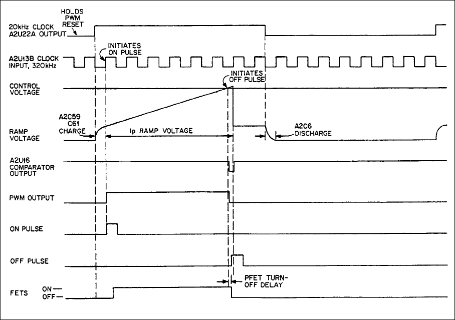
48
Figure 4-4. PFET Control Signals Timing Diagram
Constant-Voltage (CV) Circuit
The Constant-Voltage Circuit compares the output voltage to the user-set CV PROGRAM Voltage to produce the CV
CONTROL Voltage. Two comparison amplifier loops accomplish the comparison. In the outerloop, CV Error Amplifier
A2U8 compares V-MON, a buffered fraction of the sensed output voltage OVS, to the program voltage from the CV
Programming Switches to create the CV ERROR Voltage. Then in the innerloop, Innerloop Amplifier A2U10A compares
this error voltage to IVS, a buffered fraction of the innerloop output voltage, to produce the CV CONTROL Voltage. The
CV ERROR Voltage is also diode-OR connected through diode A2CR21 as an input to the Down Programmer.
V-MON also connects through protective circuitry to rear-panel terminal VM for remote monitoring of the output voltage.
It is equal to 1/4 of the sensed output voltage OVS, and is 5Vdc for 60Vdc full output.
Settings of the CV Programming Switches, the B6, B5, and B4 MODE switch settings allow the CV PROGRAM Voltage
to come from the front-panel VOLTAGE Control; from an external voltage applied between rear-panel terminals VP and
sP; or from an external resistor between VP and sP. When using either the VOLTAGE Control or external resistor,
current from the CV Constant-Current Source flows through the applicable resistance to develop the CV PROGRAM
Voltage.
In CV mode, the CV CONTROL Voltage varies between about -0.5Vdc and about + 1.0Vdc. It is most negative when the
load is drawing no power. As the load draws more power, the voltage becomes more positive. The CV CONTROL Voltage
is at the cathode of diode A2CR24, part of the diode-OR input to the Control-Voltage Comparator. Diode A2CR20 prevents
voltage overshoots during transient load changes and program changes.


