


12
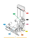
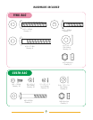
AC1
AC1
AC2
AC2
AT1
AT1
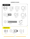
AG3
AG3
AF2
AF2
AH1
AH1
2
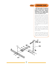
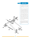
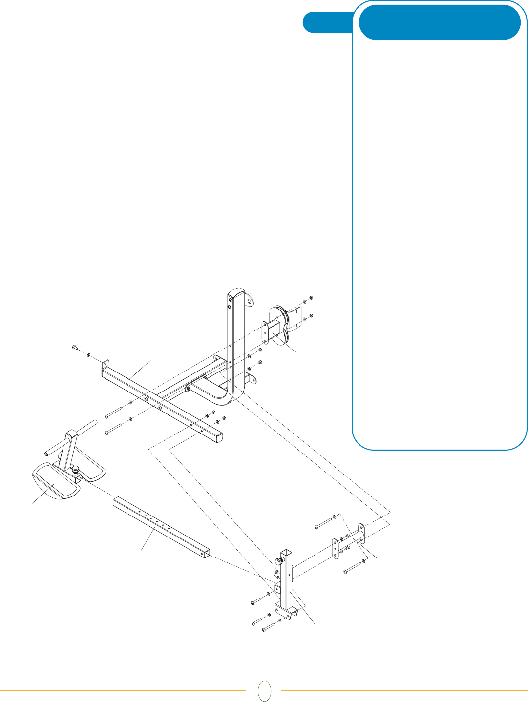
STEP
• Place seat post support (AT1) on the side
floor support (AC1) and attach with two
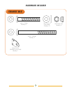
bolts (M10x75), four flat washers
(10.2x22x2), and two nylon nuts (M10).
Partially thread pull pin onto seat post sup-
port.
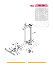
• Slide the frame connection tube (AG3)
between the seat post support (AT1) and
swing arm support (AG2). Attach it to the
seat post support with two bolts (M10x10)
and two flat washers (10.2x22x2). Attach
the opposite end to the frame connection
tube with two bolts (M10x120), four flat
washers (10.2x22x2), and two nuts (M10).
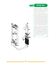
• Slide the foot support base (AH1) onto
foot support tube (AC2). Tighten pull pin in
one of the adjustment locations of tube.
Place end of support tube (AC2) into
bracket on seat post support (AT1). Attach
seat post support end with one bolt
(M10x65), two flat washers (10.2x22x2),
and one nylon nut (M10). Attach the
opposite end to the floor support (AC2)
using one bolt (M10x25) and one flat
washer (10.2x22x2).
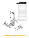
• Attach the dual pulley bracket assembly
(AF2) onto the swing arm support, with
plate side facing as shown in diagram.
Use two bolts (M10x120), four flat washers
(10.2x22x2), and two nylon nuts (M10)
to secure.
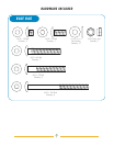
BLUE BAG