


Test Procedures
3-32
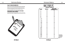
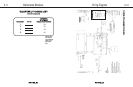
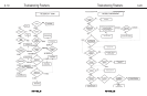
VVOOLLTTAAGGEE TTOO IINNCCLLIINNEE MMOOTTOORR TTEESSTT
This test is utilized in conditions of No Incline Movement, Incline Fluctuation, or E1: Stall.
Set Voltmeter to AC Volts. To access incline plug, PWM screws may need to
be removed.
Place voltmeter leads across White and Black while pushing UP button
120 Vac indicates normal PWM output, 0Vac signals no output
Place voltmeter leads across Red and White while pushing Down button
120 Vac indicates normal PWM output, 0Vac signals no output
Test Procedures
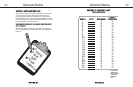
TTRREEAADDBBEELLTT TTEENNSSIIOONN TTEESSTT
This test will address belt slipping and is used in any roller replacement or deck
replacement. Ensure that the drive belt is properly tensioned before adjusting treadbelt
tension. Belt and Deck wear and/or lack of lubrication can cause the treadbelt to show
symptoms similar to loose treadbelt tension- check these conditions before adjusting
treadbelt tension.
Turn treadmill on and adjust speed to 2 mph
Walk heavily on the belt pulling slightly against belt movement
If hesitation or slip is detected, tighten treadbelt tension bolts 1/4 turn
Repeat until no hesitation or slip is encountered. Check at higher speeds
Treadbelt tension is too tight if the belt feels stiff to touch with no give or the belt groans
against rollers. You should be able to insert your hand between the belt and deck palm up
almost to your thumb when the belt is at proper tension.
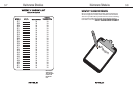
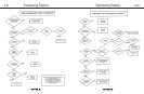
IINNCCLLIINNEE PPOOTTEENNTTIIOOMMEETTEERR CCAALLIIBBRRAATTIIOONN TTEESSTT
This test can correct E1: Minimum conditions and aid in diagnosis of incline problems
with finding zero or target incline.
Set voltmeter to Ohms (Ω) with treadmill unplugged from wall
Place 1 voltmeter lead on pin 3 (Blue) and 1 lead on pin 2 (Orange)
Check for 800 Ohms
In calibration mode before pressing Start, the Distance window displays
the incline number. With the treadmill at zero, the number should be between
160 and 180. 0 often indicates a wire harness misconnection or failure of
signal to panel. As the unit inclines during calibration, watch the numbers in
the Distance window, if they do not increase by at least 60 from the zero value, an
E1:Range error will result. Then the zero value may need to be reset to a lower value.
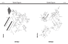
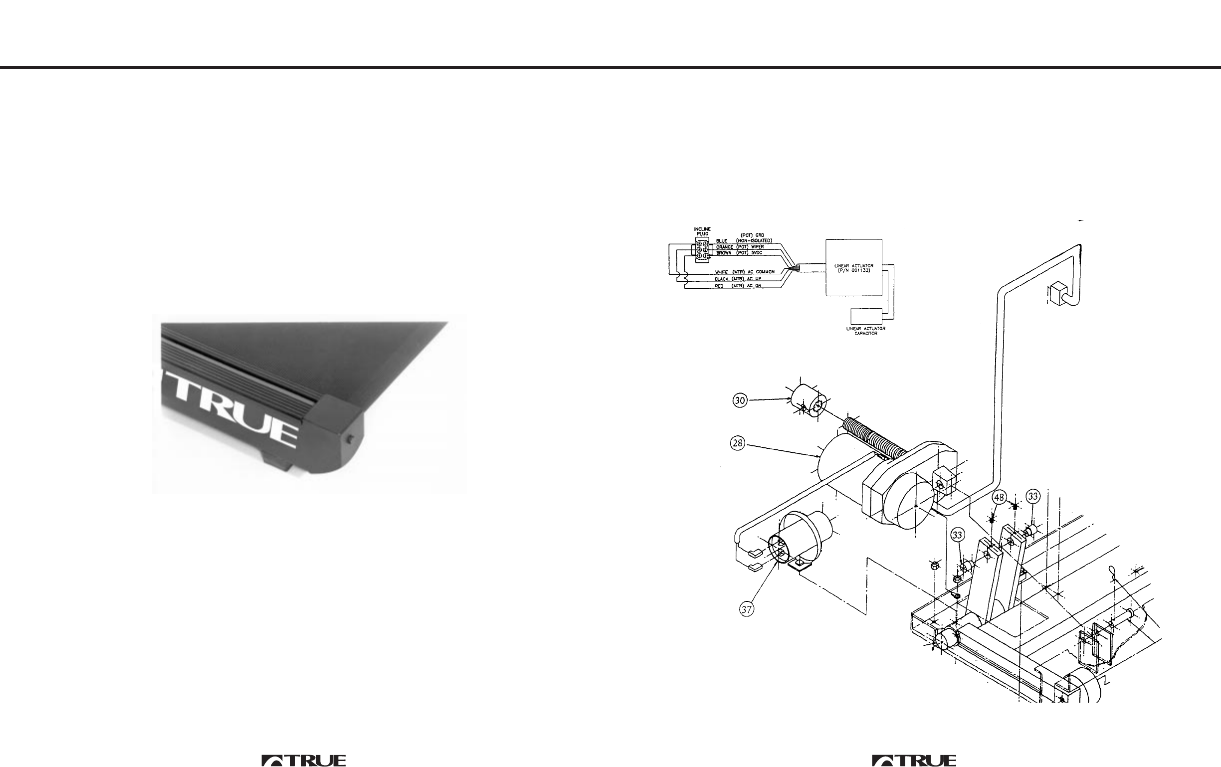
If incline potentiometer needs adjustment, remove swivel pins and twist incline motor
shaft by hand until the 800 Ohms is reached. See diagram on next page.
3-31