


9
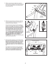
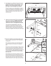
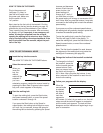
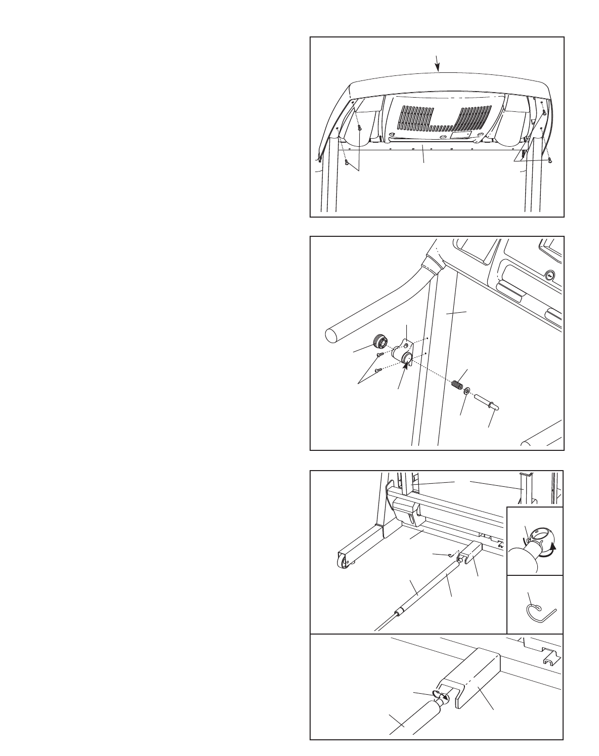
8. Hand tighten four additional Screws (3) into the
H
andrail (20) and the console assembly. Then,
tighten all nine Screws used in step 7 and
this step; do not overtighten the Screws.
P
lug in the power cord as described on page 11,
and turn on the power as described on page 13.
Note: The treadmill may automatically rise to the
maximum incline level and then return to the
minimum level.
Console Assembly
3
20
8
3
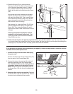
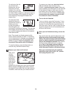
10.Place the treadmill in the storage position (see
HOW TO FOLD AND MOVE THE TREADMILL
on page 24).
Next, place the cylinder end of the Shock (92)
near the bracket on the base of the Uprights
(84).
See the two small inset drawings. Using your fin-
gernail or the end of a screwdriver, press on the
end of the Shock Pin (25) to loosen it from the
Shock (92). Next, rotate the Shock Pin and pull it
out of the Shock. Be careful to avoid losing
the Shock Pin.
See drawing 10a. Press the cylinder end of the
Shock (92) onto the ball on the bracket. Next, in-
sert the end of the Shock Pin (25) through two of
the small holes in the end of the Shock. Then,
rotate the Shock Pin until it clips onto the Shock.
92
25
92
25
10
10a
84
58
Bracket
Cylinder
Bracket
25
25
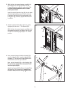
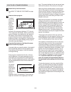
9. Attach the Latch Housing (73) to the left Upright
(84) with two Screws (3). Make sure that the
large hole in the Latch Housing is on the
side shown. Do not overtighten the Screws.
If the pin is not preassembled in the Latch
Housing (73), remove the knob from the pin.
Make sure that the collar and the spring are on
the pin as shown. Insert the pin into the Latch
Housing, and tighten the knob back onto the pin.
3
84
9
Knob
Pin
Collar
Large
Hole
Spring
73