


10
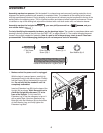
12. Make sure that all parts are properly tightened before you use the treadmill. Note: Extra hardware may
be included. Keep the included hex keys in a secure place; the large hex key is used to adjust the walking belt
(see page 27). To protect the floor or carpet, place a mat under the treadmill.
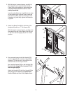
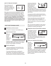
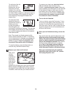
1. Remove the key from the console and unplug
the power cord.
Remove the Screw (3) and the Access Door (76)
from the back of the Console Base (85).
2. Connect the wire on the receiver (A) to the indi-
cated wire extending from the Console Base
(85). Hold the receiver so the small cylinder is
oriented as shown and is facing the Console
Base.
Attach the receiver to the plastic posts on
the Access Door (76) with the two included small
screws.
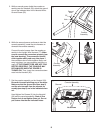
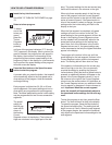
3.
Make sure that no wires are pinched. Reattach
the Access Door (76) with the Screw (3). Discard
the other wires included with the receiver.
If you purchase the optional chest pulse sensor (see page 23), follow the steps below to install the receiver
included with the chest pulse sensor.
A
85
Small
Cylinder
3
76
Wire
Small Screws
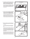
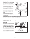
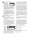
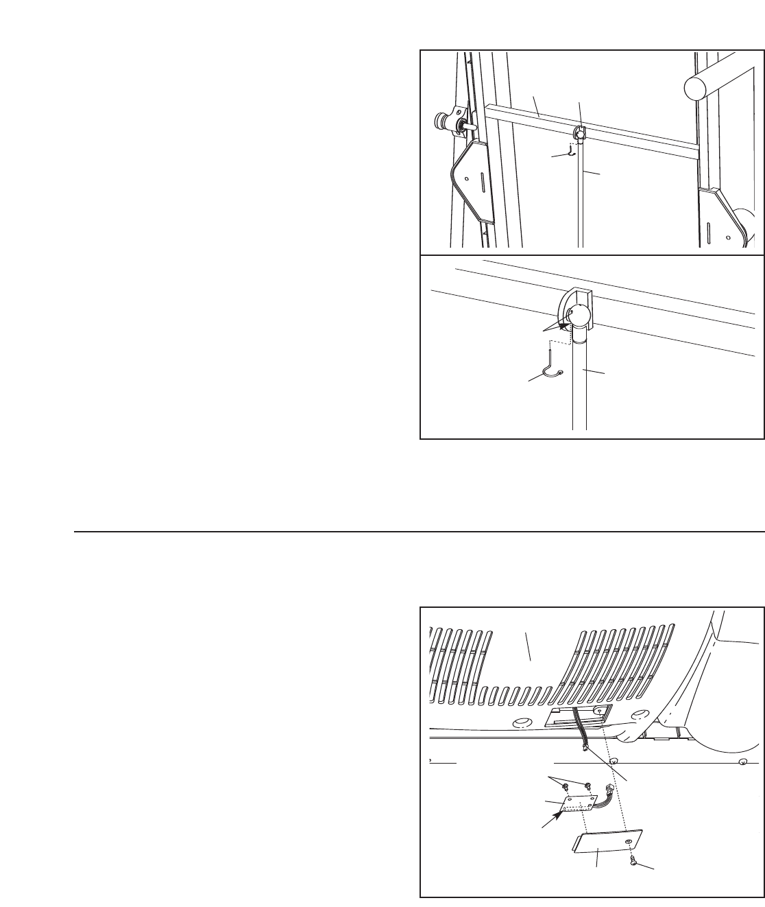
11.Raise the Shock (92) to a vertical position.
Remove the Shock Pin (25) from the raised end
of the Shock as described in step 6. If neces-
s
ary, rotate the Shock to align the end of the
Shock with the ball on the bracket on the Frame
(58).
N
ext, press the Incline increase and decrease
b
uttons until the ball on the bracket is aligned
with end of the Shock (92). Then, press the end
of the Shock onto the ball. Note: It may be nec-
essary to press the end of the Shock onto the
ball while the Frame is moving.
See drawing 11a. Insert the Shock Pin (25) into
the two indicated small holes in the end of the
Shock (92). Then, rotate the Shock Pin until it
clips onto the Shock. Note: Extra Shock Pins are
included.
Press the Incline decrease button until the
treadmill is at the lowest incline level.
Then,
unplug the power cord and lower the treadmill
Frame (58) to the floor.
25
92
Holes
25
92
11
11a
58
Bracket