


704101
30.
34.
3~.
36.
REGGIE WHITE ALL PRO SYSTEM ASSEMBLY INSTRUCTI[ONS
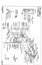
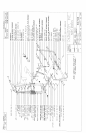
To install the HIGH PULLEY CABLE. start by routing the end of the CABLE WITHOUT the WHITE
BALL over the TOP PULLEY on the PULLEY MOUNT FLATS. After the CABLE haz been routed:~e hole in front
SECURELY assemble one (1) 3/8 X ,.-~4 IN. BOLT, and one (I) 3/8 IN. LOCK NUT
of the PULLEY on the PULLEY MOUNT FLATS. (DO NOT OVER TIGHTEN THIS BOLT)
Run CABLE over and down the SECOND PULLEY of the PULLEY MOUNT FLATS. Run the
CABLE around one of the PULLEYS of the PULLEY BLOCK and up to the THIRD PULLEY of the
PULLEY MOUNT FLATS.
Pall CABLE over and down the THIRD PULLEY. to the CARRIAGE and a::ach the CABLE to the
CARRIAGE, using one (1) QUICK LINK. (SEE DETAIL
See CABLE ROUTING DIAGRAM for help in completing this step.
To install LOW PULLEY CABLE, start by inserting the end of the CABLE ~,~,ITHOUT the WHITE
BALL under the FRONT PULLEY of the UPRIGHT FRAME. After the CABLE has ~en routed
SECURELY assemble one (1) 3/8 X 2-3/4 IN. BOLT, and one (I) 3/8 lN. LOCK NUT to :he hole
underneath the FRONT PULLEY. (DO NOT OVER TIGHTEN THIS BOLT)
Run the CABLE back to and around the second PULLEY behind the FRONT PULLEY- After the
CABLE has been routed, position the CABLE RETAINING CLIP in a vertical positior~ :ader the
PULLEY and CABLE and tighten the PULLEY CONNECTION completel).
Run the CABLE up to and around the BOTTOM PULLEY on the PULLEY BLOCK. (NOTE: THE
CABLE MUST BE ROUTED AROUND THE BOTTOM PULLEY FROM THE REAR "FO THE
FRONT)
Run the CABLE down to and around the PULLEY behind the SMALL SEAT PAD on ,2~e UPRIGHT
FRAME and attach the end of the CABLE to the PULLEY BRACKET of the LOOP CABLE. using one
( 1 ) QUICK LINK. After the CABLE has been routed, position the CABLE RETAINING CLIP in
vertical position under the PULLEY and CABLE and tighten the PULLEY CONNECTION completely.
See CABLE ROUTING DIAGRAM for help in completing this step.
Tighten the PULLEY CONNECTIONS of the PULLEY BLOCK.
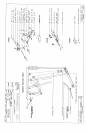
Insert one (1) I-3/4 IN. SQ. END CAP into the end of the BENCH TOP, and fi’,ree (3) 1-~.4 IN. SQ.
CAPS into the ends of the FRONT LEG as shown on drawing.
SECURELY assemble the BENCH TOP to the FRONT LEG as shown on drawing, us:.:g I:wo (2) 3,’8
2-3/4 IN. BOLTS, four (4) 3/8.IN. WASHERS, and two (2) 3 8 IN. LOCK NUTS.
Insert three (3) 1-3/4 IN. SQ. END CAPS into the ends of the REAR LEG as shown on ~:-awing.
Assemble the REAR LEG to the BENCH TOP as shown on drawing, using one (1) 3/8 X 3 IN. BOLT
four (4) 3/8 IN. WASHERS, and one (I) 3/8 IN. LOCK NUT. (TIGHTEN THE CONNECTION
ENOUGH TO REMOVE THE PLAY, YET ALLOWING THE REAR LEG TO ROTATE
FREELY)
7
I IF21/95