


704101 REGGIE WHITE ALL PRO SYSTEM ASSEMBLY INSTRUCT, IONS~
21.
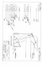
Insert the LEFT and RIGHT PEC DEC ARMS through the 1/2 IN. FLANGE BEARINGS in the
BEARING HOUSING on their respective sides as shown on drawing, and SECURE them in place with
two (2) ~ 2 IN. ID. PRESS-ON CAPS.
22.
Slide tx~o (2) 4 X 12 ROLLER PADS onto :he LEFT and RIGHT PEC DEC ARMS until the ROLLER
PAD is ,:LUSH with the bottom of the ARMS. (IF A LUBRICANT IS REQUIRED, COAT THE
INSIDE OF THE ROLLER PAD WITH RUBBING ALCOHOL. ALSO, ROTATING THE PAD
WHlLE PUSHING UP WILL HELP TO EASE ASSEMBLY)
23.
Attach ~wo (2) CARRIAGE GUIDES to the CAM STOP on the BEARING HOUSING where the CAMS
of the PEC DEC ARMS contact the CAM STOP.
24.
LOOSELY assemble two (2) 3-1/2 IN. PULLEYS, and two (2) CABLE RETAINING CLIPS to
PLATES of the BEARING HOUSING as shown on drawing, using two (2) 3/8 X 2 IN. BOLTS, P, vo (2)
3/8 IN. WASHERS, and two (2) 3/8 IN. LOCK NUTS. (NOTE: THIS CONNECTION WILL
TIGHTENED AFTER THE CABLE HAS BEEN ROUTED)
25.
SECURELY assemble the SMALL BACK PAD to the UPRIGHT FRAME as shown on drawing, using
two (2) 3/8 X 2-I/2 IN. BOLTS, and two (2) 3/8 IN. LOCK WASHERS.
26.
SECURELY assemble one (I) 3-1/2 IN. PULLEY, and two (2) 3/8 IN. SPACERS in betwee:~
PLATES at the bottom of the UPRIGHT FRAME as shown on drawing, using one (I) 2-3/4 IN. BOLT,
and one ~1) 3/8 IN. LOCK NUT.
27.
LOOSELY assemble two (2) 3-1/2 IN. PULLEYS, and two (2) CABLE RETAINING CLII?S to
PLATES of the UPRIGHT FIL,~ME as shown on drawing, using two (2) 3/8 X 2 IN. BOLTS, two (2)
IN. WASHERS, and two (2) 3/8 IN. LOCK NUTS. (NOTE: THIS CONNECTION WILL
TIGHTENED AFTER THE CABLE HAS BEEN ROUTED)
28.
LOOSELY assemble p, vo (2) CONNECTOR PLATES around two (2) 3-1/2 IN. PULLEYS;. using t~,vo
(2) 3/8 X 2 IN. BOLTS, and two (2) 3/8 IN. LOCK NUTS. (NOTE: THIS CONNECTIOt~’ WILL
TIGHTENED AFTERTHE CABLE HAS BEEN ROUTED)
NOTE:
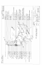
BEFORE PROCEEDING WITH CABLE INSTALLATION, UNRAVEL CABLES, AND REMOVE
AS MUCH SPIRALING AS POSSIBLE.
29.
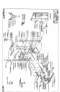
To ins:zll LOOP CABLE, start by inserting the BALL ENDS of the CABLE into the BUSHINGS on the
CAMS ofthe LEFT and RIGHT PEC DEC ARMS.
Drape ~oth sides of the CABLE o(,er the PULLEYS on the BEARING HOUSING. Position CABLE
RETAINING CLIPS in a vertical positior, over the PULLEY and CABLE, after the LOOP CABLE has
been routed. Tighten the PULLEY CONNECTION completely.
¯
Place one (1) 3-I/2 IN PULLEY into the LOOP of the CABLE created from the above stel:,, and
SECURELY assemble the PULLEY BRACKET to the PULLEY, using one (1) 3/8 X 1-3,4 IN. BOLT,
and one (1) 3/8 IN. LOCK NUT. (NOTE: MAKE SURE THAT THE CABLE IS IN TE[E GROOVE
OF THE PULLEY BEFORE TIGHTENING)
¯
See CABLE ROUTING DIAGRAM for help in completing this step.
6
1 I,°-1/95