


705101
REGGIE WHITE ALL PRO GYM ASSEMBLY INSTRUCTIONS
9.
]0.
]2.
]3.
14.
]5.
16.
17.
18.
19.
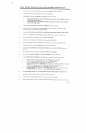
Slide two (2) 2 1-N. SQ. COVER CAPS over the ends of the BASE as shown on drawing.
Insert ali END CAPS into the WELDMENTS as shown on drawing.
SECURELY assemble the UPRIGHT to the BASE as shown on drawing.
BEFORE TIGHTENING CONNECTION MAKE SURE THAT THE UPRIGHT FRAME
IS SQUARE TO THE BASE.
MAKE SURE BOLTS GO THROUGH THE BASE FIRST AND THAT LOW HEIGHT
LOCK NUTS ARE USE]).)
Attach the SEAT SUPPORT to the BASE and UPRIGHT as shown in drawing.
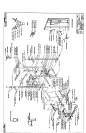
Assemble PULLEYS to the inside of the TOP BOOM as shown in DETAIL B and string CABLE
6571001 as shown in CABLE ROUTING DIAGRAM.
Attach the TOP BOOM to the UPRIGHT. (MAKE SURE CABLE RUNS OVER TOP OF BOLTS)
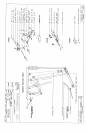
¯ Insert two (2) WEIGHT PLATE BUSHINGS into each WEIGHT PLATE as shown in DETAIL
Insert GUIDE RODS and WEIGHT STACK CUSHIONS into BASE.
CAREFULLY slide fifteen (15) WEIGHT PLATES onto the GUIDE RODS.
Assemble the HEAD PLATE and WEIGHT STACK SHAFT and slide it onto the GUIDE RODS.
Attach GUIDE RODS to the TOP BOOM using two (2) NYLON BOLTS.
Attach the LEG EXTENSION and ROLLER PAl) SWIVEL to the SEAT SUPPORT as shown in
DETAIL C.
Attach the SEAT and BACK PADS to the SEAT SUPPORT and UPRIGHT.
Attach two (2) RUBBER BUMPERS to the SEAT SUPPORT as shown in DETAIL
To attach PRESS ARM ASSEMBLY to fl~e BASE, follow assembly drawing and these steps:
Insel-~ the SHAFT and two (2) 3/4 IN. FLANGE BEARINGS into the BASE.
LOOSELY attach the CROSS BRACE to one of the PRESS ARMS.
Attach this PRESS ARM to the SHAFT using a SET SCREW.
(NOTE: Make sure that the CROSS BRACE is resting on the RUBBER BUMPER of the SEAT
SUPPORT and positioned so that the bottom tab is closer to the rear of the gym.)
Attach the other PRESS ARM to the CROSS BRACE and the SHAFT.
IN THIS ORDER, press the bottom of the PRESS ARMS together against the locking collars
and tighten both SET SCREWS, then center CROSS BRACE and tighten bolts.
AT THIS TIME TIGHTEN ALL LOOSE FRAME CONNECTIONS MADE TO THIS POINT.
Assemble two (2) PULLEYS to the 5-1/4 PLATE as shown on drawing.
LOOSELY assemble all remaining PULLEYS to the gym as shown on drawing.
String CABLE 6575601 as shown in CABLE ROUTING DIAGRAM, looping it with the top cable using
3
] 2/4/95