


704101 REGGIE WHITE ALL PRO SYSTEM ASSEMBLY INSTRUCTIC~NS
10.
11.
12.
13.
14.
15.
16.
17.
18.
19.
20.
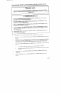
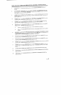
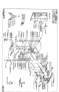
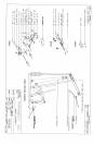
Insert three (3) I-_: -: IN. SQ. END CAPS into the ends of the BEARING HOUSING as shown
drawing.
Slide the BEARING HOUSING down over the FRONT UPRIGHT of the UPRIGHT FRAME to the
first set of holes ~ sb, own on drawing. SECURELY assemble it to the UPRIGHT using two (2) 3/8 X
3/4 IN. BOLTS, a.-.d ~vo (2) 3/8 IN. LOCK NUTS.
LOOSELY asser=.z:.e three (3) 3-1/2 IN. PULLEYS. and six i5) 3/8 IN. SPACERS in between the two
PULLEY MOUNT FLATS as shown on drawing,, ";’ 2 three (3) 3/8 X 2-.~/4 IN. BOLTS. and three (3)
3/8 IN. LOCK NU’TS.
LOOSELY asse.-..~:,e the PULLEY MOUNT FLAT ASSE~IBLY to the UPRIGHT FRAMF as shown
on drawing, using v,~o (2) 3/8 X 2-3/4 IN. BOLTS, and two (2) 3/8 IN. LOCK NUTS.
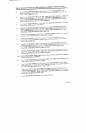
LOOSELY assembIe the HORIZONTAL SUPPORT in bev,~een the PULLEY MOUNT Ft,ATS as
shown on drawin2-, asing one (1) 3/8 X 2-3/4 IN. BOLT, and one (1) 3/8 IN. LOCK
Attach thirty-two ~,32) PARAGLIDE STRIPS to the :,so (2) BAR HOLDERS and the two (2) SAFETY
RAILS as shown :,r. (DETAIL A) using the following steps:
A.
Thorou~.’.i’: clean all inside surfaces where :ine PAR-~,GLIDE
S
are to be attached.
B.
Remove 2~e PARAGLIDES from paper backing the and firmly apply them to all shown surfaces
(8 places
~
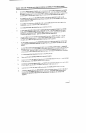
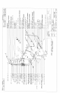
SECURELY Assemble four (4) SPRING PIN ASSEMBLIES to the SPRING PIN BARRELS, of the two
(2) BAR HOLDERS and the two (2) SAFETY RAILS as shown in (DETAIL B). (!!! I;MPORTANT
TIGHTEN THE NUT OF THE SPRING PIN ASSEMBLY SECURELY)
Pull back the SP~.NG PIN on the SAFETY RAILS and slide one down over each UPRIGHT as shown
on drawing. Eng=ge the SPRING PIN into a desired ~djustment hole.
Pull back the SP,~NG PIN on the BAR HOLDERS and slide one down over each UPRIGHT as shown
on drawing. Engzge the SPRING PIN into a desired adjustment hole.
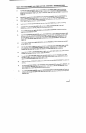
LOOSELY asse:..,z[e the two (2) UPRIGHT ASSEMBLIES .:o the BASE as shown on drawing, using four
(4) 3/8 X 2-3/4 IN. BOLTS, and four (4) 3/8 IN. LOCK NUTS.
LOOSELY asse.-.,b!e the two UPRIGHTS to the ends of the HORIZONTAL SUPPORT a~; shown on
drawing, using v.~ z (2) 3/8 X 2-3/4 IN. BOLTS, fou: (4) 3/8 IN. WASHERS, and two (2) 3i8 IN.
NUTS.
AT THIS TIME TIGHTEN ALL LOOSE FRAME CONNECTIONS MADE TO THIS POINT.
Insert four (4) 2 ~. SQ. END CAPS into BOTH ENDS of the LEFT, and RIGHT PEC DEC ARMS
shown on drawing.
Insert four (4) 1 2 ~. FLANGE BEARINGS into the BUSHINGS of the BEARING HOUSING,
shown on drawing.
5
11/21/95