


10.
I1.
12.
14.
’ ~* Remove the PAPA.GLIDE ST/UPS from the paper backing and firmly apply them tO all shown surfaces.
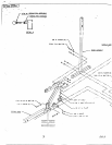
,Carefully slide the PRESS ADJUSTMENT TUBE into the RECEIVING TUBE. (MAKE SURE"],’HE SPRING PIN
BARREL ON THE RECEIVING TUBE IS ON THE SAME SIDE AS THE HOLES IN THE PF~SS ADJUSTM~IlNT
TUBE)
Insert two (2) 1/2- IN. FLANGE BEARINGS into the PRESS LEVER as shown on drawing.
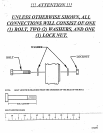
Assemble the PRESS ADJUSTMENT TUBE to the PRESS LEVER as shown on drawing, using one (1) 1/2 X
BOLT, two (2) 1/2 IN. WASHERS, and one (1) I/2 IN. LOCK NUT. (TIGHTEN THE CONNEL-i’ION ENOUGH
TO .REMOVE THE PLAY, YET ALLOWING THE RECEIVING TUBE TO ROTATE FREELY)
Insert two (2) .3/4 IN. FLANGE BEAP,.INGS into the PRESS ARM ~s shown on the drawing.
¯ ’. Hold the PRESS ARM between the. REAR and ~MIDDLE UPRIGHTS as shown in on drawing, and’sIide the I0-I/4 IN.
AXLEthrough the MIDDLE UPRIGHT,th~ PRESS.A~RM,:and.througfi the COLLAR on.the REAR UPRIGHT. To
SECURE the AXLE in place, insert two (2) 3116 X 3/8 IN. SET SCREWS, into the COLLARS on the UPRIGHTS and
tighten it down onto the AXLE. (SEE DETAIL C)
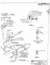
Insert two (2) I~ IN. FLANGE BEARINGS into the RECEIVING TUBE as shown on drawing.
Assemble the RECEIVING TUBE to the PRESS ARM as shown on drawing, ~tsing one (1) I/2 X 3.-I/2 IN. BOLT, two
1/2 IN. WASHER.S, and one (I) 1;2 IN. LOCK NUT. (TIGHTEN THE CONNECTION ENOUGIt TO REMOVE
PLAY,.YET ALLOWING THE PRESS ARM TO ROTATE FREELY)
Assemble the PUSH/PULL CABLE to the SPRING PIN HOUSING and to the L-BRACKET on fl~e RECEIVING
TUBE as shown in (DETAIL D), using the f’ollowing steps:
¯
Thread the first I/4-2~i IN. NUT to the bottom of the threaded end of’the CABLE. Allow
¯
other I/4-28 IN. NUT to hang loose on the exposed CABLE .until the SPRING PIN ASSEMBLY is attached.
¯
Securely assemble the SPRING PIN ASSEMBLY to the SPRING PIN BARREL. (!:! IMPORTANT !!!
TIGHTEN THE NUT OF THE SPRING PIN ASSEMBLY SECURELY)
¯
Swing the PRESS ARM up until the SPRING PIN of’the PUSH/PULL CABLE engages in one of the
adjustment holes.
¯
Thread the second I/4-25 IN. NUT onto the threaded end of the CABLE, and cinch the two (2) 114-2~ .IN.
around the fiat.
¯ Use the extra thread on the end of.the CABLE’to adjust out slack, ( !!! DO NOT ADJUST OUT TO FAR 1!!
ALWAYS ALLOW SPRING PIN ASSEMBLY TO FULLY ENGAGE)
¯
Attach one (1) ADHESIVE CLIP to the RECEIVING TUBE and snap the CABLE into it.
"SECURELY tighten all loose frame cormectiot~s made to this point. (!!! IMPORTANT !!! TO ASSUR~ PROPER "
.:~FUNCTION OF THE 425, THE LOOSE FRAME CONNECTIONS MUST BE TIGHTENED IN THE FOLLOWING
ORDER) Tighten the:
¯ REAR UPRIGHT to the BASE and to the TOP BOOM.
¯ PRESS BASE to the REAR and MIDDLE UPRIGHTS.
¯ PRESS BASE to the BASE.
.= MIDDLE UPRIGHTto the BASE’and to the .TOPBOOM.
¯ FRONT. UPRIGHT to the.BASE.
NOTE: DO NOT TIGHTEN THE FRONT UPRIGHT TO THE TOP BOOM AT THIS TIME,
SECURELY assemble the other BACK/SEAT PAD to the FRONT UPRIGHT as shown on drawing, using two (2) 3/~
.3 IN. BOLTS, two (2) 3/8 IN. LOCK WASHERS, and two (2) 3/g IN. WASHERS.
THIS CONCLUDES THE ASSEMBLY OF (LEVEL 4)
9
07/22/96