


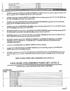
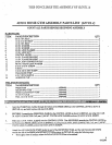

COUNT ALL PARTS BEFORE BEGINNING ASSEMBLY
ITEM NA~[E/DESCRIPTION
QTY
""’",
I/4 IN. WASHER
1
.,..
I!,1-28 IN. NUT ....................................................................................................................................................
2
.3. KEYHOLE CLEVIS ............................................................................................................................................
2
4.
SNAP LINK ............................................................................................................................
. .............................
2
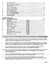
~,VELDMENTS/PARTS:
ITEM
NAME/DESCRIPTION
QTY
1. D-P.ING ........................................................................
:..(6540301) ........................ , ........................., ................
1
2.
D-RING CABLE ...: ....................................................... :.(656890"I).~ ..................................................................
i
3. .LAT CABLE ....................................................................
(6535901) ....................................................................
!
4. ,,MULTI-PKESS ,CABLE ...................................................
(653600.1.) .................................................: .................
I
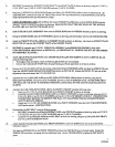
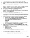
* ~T.H.E~ .S~rRU C’T.I O N..S.~FO R (/,,E.. V~J,, "6) ,~RF~To ~BE,.USED
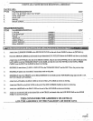
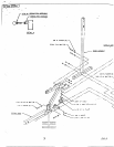
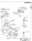
1. To assemble the D-RING CABLE, follow the cable routing diagram shown in (DETAIL A), and use.the following steps:
¯
SECURELY’ assemble the D-RING CABLE to the WEIGHT STACK SHAFT of the HEAD PLATE as.shown on
drawing.
-.
" "-". ...................
¯
Route the CABLE up and over the two (2) PULLEYS in the LAT BOOM abbve the WEIGHT STACK.
(REMOVE PULLEYS FOR EASE OF INSTALLATION)
¯
LOOSELY assemble the D-RING to the D-RING CABLE as shown on drawing, using one (I) 1/4 IN. WASHER,
and two (2) 1/4-28 IN. NUTS. (LOCATE 1/4-28 NUTS HALF WAY UP ON THE THREADS OF THE D-RING
CABLE. DO NOT TIGHTEN NUTS AT THIS TIME)
*
SECURELY Tighten the two (2) PULLEY connections from the SECOND STEP.
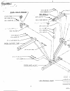
2 To. assemblethe LAT CABLE, follow the cable routing diagram on drawing, and use the following st~.’ps:
¯ . Attach one (I) SNAP LINK to the ball end of the LAT CABLE.
¯
Remove the two bolts in the FRONT UPRIGHT and TOP BOOM connection.
.. Route the LAT CABLE as shown on drawing and in (DETAIL B). (REMOVE PULLEYS FOR EASE
INSTALLATION)
¯
Run the LAT CABLE through the hole ofthe D-RING as shown in (DETAIL B) and attach one (I) KEYHOLE
CLEVIS to the end of the LAT CABLE.
,*
Replace and SECURELY tighten the two (2) PULLEY and two (2) BOLT comiections from the previous steps.
(IMPORTANT: NL-kKE SURE THE LAT CABLE RUNS OVER THE TOP OF THE BOLTS IN THE TOP
BOOM !!!)
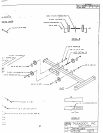
¯ ..’to assemble the MULTI-PRESS CABLE, follow the cable routing diagram shown .in drawing and use the following steps:
¯
Attach one .(I) SNAP LINK to the ball end of the MULTI-PRESS CABLE.
¯
Run the MULTI-PRESS CABLE through the hole of the D-RING as shown in (DETAIL B) a6d attach one (I)
KEYHOLE CLEVIS to the end of the MULTI-PRESS CABLE.
THIS CONCLUDES .THE.ASSEM.BLY-OF (LEVEL 6)
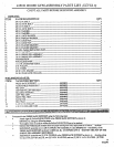
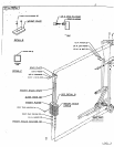
425101 HOME GYM ASSEMBLY PARTS LIST (LEVEL 7)
COUNT ALL PARTS BEFORE BEGINNING ASSEMBLY