


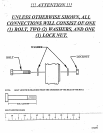
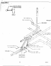

SECURELY assemble the WEIGHT sTACK SHAFT to the HEAD PLATE as shown on drawing, using one (I) 3/2 X
1~ IN. BOLT, one (1) 3/8 IN. LOCK WASHER, and one (I) 3/8 IN. WASHER.
Snap two (2) W3~IGHT PLATE BUSHINGS each, into fiReen (}5) WEICHT PLATES shown in (DETAIL B).(IF
ASSEMBLING A 200 LB. STACK AT THIS TIME, SNAP TWO (2) WEIGHT PLATE BUSHINGS EACH INTO
THE RE.~tAINING FIVE (S) WEIGHT PLATES)
USING EXTRE~TE CARE slide all fifteen (or twenty) WEIGHT PLATES down over the CUIDIE RODS onto the
WEIGHT STACK CUSHIONS as shown on drawing. (MAKE SURE THAT THE KEY HOLES OF THE WEIGHT
PLATES ARE ALL FACING THE SAME WAY)
Slide t~e HEAD PLATE ASSEMBLY down over the GUIDE RODS onto the WEIGHT STACK as shown on drawing.
Swing th~ GUIDE RODS under the TOP BOOM as shown on drawing, and hold in place with two (2) GUIDE ROD PINS.
¯
Auach the-WEIGHT STACK-LABELS to the ..W.EIGHTSTACK:as shown on.drawing. Also .insertthe WEIGHT STACK
SELECTOR PIN into the first WEIGHT PLATTE of the WEIGHT STACK.
II.
12.
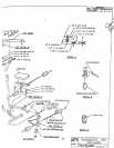
SECURELY Assemble one (I) ~/8 IN. SPRING PIN ASSEMBLY to the SPRING PIN HOUSING, of the LEG
CURL/~XTENSION ARM as shown in (DETAIL C). (Ill IMPORTANT !!! TIGHTEN THE NUT OF THE SPRING
PIN ASSEMBLYSECUREL@.
Attach eight (8) PAKAGLIDE STRIPS to the AD.IUSTABLE ROLLER PAD SLEEVE as shown in (DETAIL D),
.using the. following steps:
¯
Thoroughly clean all surfaces where the PARAGLIDE STR/PS are robe attached.
~
.Remove the PAKAGLIDE STRIPS from the paper backing and firmly apply them to all showa surfaces.
13.
15.
16.
17.
Remove the 2 IN. SQ. END CAP from the bottom of the LEG CURL EXTENSION AR~,I, pull back the SPRING PIN, and
Insert the ADJUSTABLE ROLLER PAD SLEEVE as shown in (DETAIL E). Release the SPKI’NG, PIN into one of the
adjustment holes, and reinsert the 2 IN. SQ, END CAP.
Assemble the two (2) ROLLER PADS to the LEG CURL EXTENSION ARM as shown on drawing using one (I)
ROLLER PAD SHAFT, two (2) PLASTIC WASHERS, and two (2) 9/I 6 MUSHROOM CAPS. (MAKE SURE
THE ROLLER PAD SHAFT IS INSERTED THROUGH LARGE HOLE ON THE ADJUSTABLE ROLLER PAD
SLEEVE)
¯ Assemble the LEG CURI./EXTENSION ARM to the FRONT UPRIGHT using the following s~eps:
¯ ". Insert twO (2) 1/2 IN. FLANGE BEARINGS to the FRONT UPRIGHT as shown
n
drawing..
¯
Assemble the LEG CURL/EXTENSION ARM to the FRONT UPRIGHT as shoum on drawing, using one (I) I/2
X 3-I14 IN. BOLT, two (2) I/2 TN. 3k’ASHERS, and one (1) I}2 IN. LOW I-I~IGI-IT LOCK NUT. (TIGHTEN
CONNECTION ENOUGH TO REMOVE THE PLAY, YET ALLOWING THE LEG CURL/EXTENSiON
ARM TO ROTATE FREELY)
¯ * Attach one (1) 1-1/4 IN. SO..RUBBER BUMPER to the FRON’r UPRIGHT whcr~ the LEG CURL/EXTENSION
ARM makes contact. (SEE DRAWING).
Pre-.assemble thePEC SEAT, using the following step’s:
¯
:SECURELY ~assemble one of.the BACK/SEAT .PADS to the PEG.SEAT as shown on drawing, using two (2) 318
3 IN. BOLTS, two (2) 3/8I"N. LOCK WASHERS, and two (2) 3/8 IN. WASHERS.
Assemble two (2) ROLLER PADS to thePEG SEAT as shown on drawing, using one (I) ROLLER PAD SHAFT,
and two (2) 9/I 6 MUSHROOM CAPS.
__I_3.: ....... .A.~.n.~c/~ht (8) PAP,.AGLIDE STR.IPS to the FRONT UPRIGHT as shown in (DETAIL F), and usilng the directions
followed ~n step I2. "
’, ......
Pull back the SPRING PIN on the FRONT UPRIGHT and insert the PEG SEAT down to desired height. Release the
SPRING PIN and allow it. to engage into the adjustment.holes. Use the THUMB SCREW ~o tighten the PEG SEAT in
place.